Allegro ICs Based on Giant Magnetoresistance (GMR)
Abstract
Allegro MicroSystems is a world leader in developing, manufacturing, and marketing high-performance integrated circuits (ICs), which incorporate high performance magnetic transducers. This whitepaper provides a basic understanding of the giant magnetoresistance (GMR) effect and how Allegro uses this technology in market-leading ICs to meet today’s application requirements.
The Giant Magnetoresistance (GMR) Effect
The GMR effect was discovered in 1988 by both Albert Fert of Unité Mixte de Physique CNRS/Thales and Peter Grünberg of Institut für Festkörperforschung Forschungszentrum Jülich GmbH. Both of these individuals won the Nobel Prize for this discovery in 2007. The fundamental principle of the GMR effect is based on electron spins. In a magnetoresistor, electron scattering rates increase or decrease as a function of the interaction of the spin state of the electrons and the magnetic orientation of the medium in which the electrons are traveling. Electron scattering increases the mean free path of the electron flow, effectively altering the resistance of the medium. In summary, a magnetoresistor is a resistor that changes its resistance value in the presence of a magnetic field.
GMR transducers are manufactured by creating a sequence of very thin layers made of different magnetic and nonmagnetic materials. The sequence and thickness of these materials enable the stack of thin films (GMR stack) to change its resistance in the presence of magnetic fields.
Over time, advances in GMR led to the development of a “spin-valve” type structure, which is what Allegro uses in their newest ICs. In a spin-valve, one of the two magnetic layers is considered a “reference” and is pinned or fixed in its orientation, and the other is called a “free” layer and is free to align with the magnetic field in the surrounding environment (see Figure 1). In typical magnetic sensor applications, this magnetic field is generated by a magnet or an electrical current, and is referred to as Bapp throughout the remainder of this document. The “spin-valve” is so named because it resembles a faucet, where the flow of water is related to the degree of rotation of the spigot. The open position for a GMR spin-valve relates to when themagnetic layers are aligned (as shown in Orientation A in Figure 1) where the resistance is lowest. The closed position (or low flow position) occurs when the magnetic layers are anti-aligned (as shown in Orientation B in Figure 1) where the resistance is highest. For any angular difference between the “reference” and “free” layers, the resistance of the GMR transducer is proportional to the cosine of this angle.
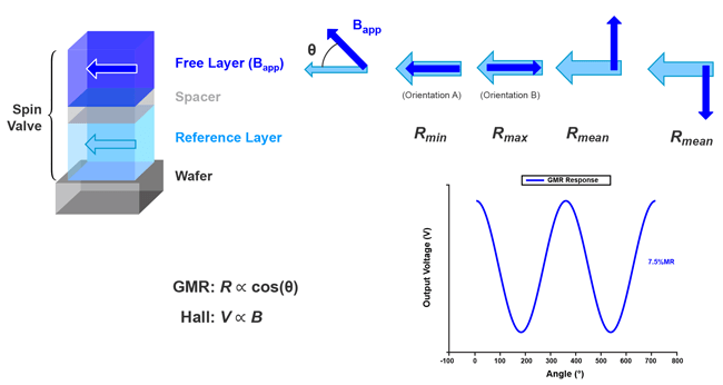
R = Rmin + (Rmin – Rmax) × cos(θ)
The % of change in resistance is called the MR%, or magnetoresistive percentage. Allegro’s GMR transducers typically have MR% in the range of 5% to 8% for the full range of field response. This level of response creates a signal about 50 times higher than Allegro’s Hall-effect transducers, enabling a higher signal-to-noise level in ICs using GMR transducers instead of Hall-effect transducers.
The GMR Response
The native response of the GMR to an applied field (Bapp) in the plane of the resistor (and therefore the die surface or IC surface) is proportional to the cosine of the angle of the applied magnetic
field. However, the resistance value of the GMR does not always indicate the strength of the field. A basic GMR transducer is more of a magnetic angle sensor (as shown in Figure 1). However, in
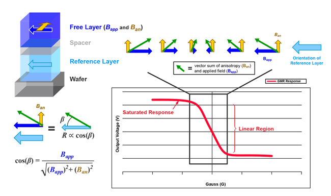
many cases, a linear response to the field in one axis is desired from a GMR transducer. In order to create this linear response, an anisotropy is created 90 degrees from the “reference” layer that
acts like another magnetic field to be vector summed with the applied field (this anisotropy-induced field, Ban, is indicated by yellow arrow in Figure 2). The response then has a linear region around the state of zero magnetic field. This method of linearizing the response is used in many of Allegro’s ICs. It is important to note the saturated response present at either extreme of the range of field response. When in a linear application, the maximum operating range is specified to account for stray magnetic field and the magnetic stimulus to be sensed. GMR product datasheets can be referenced to indicate the operating boundary conditions. One item of note is that Allegro Hall-effect solutions have no such native saturated response. Allegro’s Hall ICs have a saturated response based on application or electrical circuit conditions, not a result of the Hall technology itself.
Using GMR in an IC Application
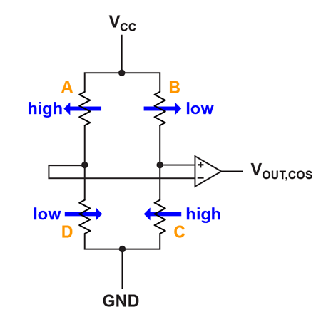
Typically, GMR resistors are created and placed in a Wheatstone bridge configuration. Half of the Wheatstone bridge (elements A and C in Figure 3) is positioned under one magnetic condition
and the other half of the Wheatstone bridge (elements B and D) is positioned under another magnetic condition. Ideally, these conditions present an equal but opposite response, allowing for the maximum output signal from the bridge. As shown by blue arrows and text in Figure 3, elements A and C sense a field in an orientation pointing left (in an anti-parallel state in this example, denoted as Rmax in Figure 1), and elements B and D sense a field in an orientation pointing right (in a parallel state in this example, denoted as Rmin in Figure 1). The result is that resistors A and C will be in a high resistance state and those in B and D will be in a low resistance state. The differential output will then be positive.
With a Wheatstone bridge, the output is always scaled with the applied VCC, and with no magnetic field applied, centers the differential output at 0 V. The differential bridge output will then swing positively or negatively according to the direction of the applied magnetic field on the Wheatstone bridge. This bridge configuration allows for both a cancellation of temperature effects and also for a level of immunity to stray magnetic field.
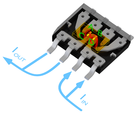
For current sensors, field is steered over elements A and C of the Wheatstone bridge in one direction, and the field over elementsB and D of the Wheatstone bridge in the opposite direction (see
Figure 4). The output of the Wheatstone bridge is fed into a differential amplifier and then through Allegro’s normal sensitivity and offset correction circuits, and possibly more advanced signal processing circuits in the analog or digital domains. In other applications where the conductor is not integrated, the physical spatial separation of the GMR elements is used to affect a differential
signal, allowing response to a variety of magnetic stimulus.
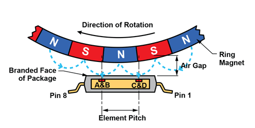
Another application for GMR is for use in ring magnet speed sensing applications such as ABS or transmission sensors. A ring of magnetic material is created with alternating north and south magnetization as shown in Figure 5. The GMR sensor may be placed under this material such that the plane of the die is horizontal. The spacing between the A and C GMR elements and B and D GMR elements creates a different magnetic field sensed by these sets of elements based on where the ring magnet is in its rotational cycle. When an N (north) pole is centered over the die, the magnetic field is pointing to the left over elements A and C and to the right over elements B and D. This will create a response on the GMR as noted in Figure 3, with a maximum positive response out of the GMR bridge. When over an S (south) pole, the response will be maximally negative. When between poles, the field is about equal for each element and the response of the bridge is near 0. This results in a sinusoidal output from the sensor as the ring magnet rotates. By counting the time between thresholds in the output over time, the speed of the ring magnet can be measured. The higher sensitivity of the GMR compared with traditional Hall sensors provides the capability for much higher air gap sensing, as well as much higher repeatability in the output for higher precision in the speed output.
Allegro Has a Monolithic GMR Solution
Many vendors selling GMR solutions do so using a multi-chip approach: a “sensor” chip and an “interface” chip. Allegro is one of very few IC manufacturers who directly integrate GMR technology
on top of their semiconductor wafers.
This integrated approach offers many advantages, including an improvement in reliability by avoiding additional die-to-die bonding, and allowing for a simpler overall design when integrating current carrying lines or positioning the elements versus an external reference.
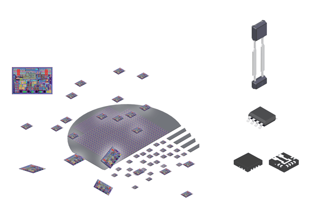
Wafers into Packages
Since Allegro’s GMR solution is monolithic in nature, GMR IC wafers are managed in the same manner as Hall-effect sensors IC wafers. The fabricated wafers are ground to the proper thickness for their packages, and the wafer is cut into the appropriate die size. Following this step, the part is packaged in Allegro’s standard range of semiconductor IC packages.
Choosing a Hall Solution or a GMR Solution
GMR transducers offer some advantages over Hall-effect transducers. However, it is very important to understand the desired application of these transducers, as in many cases a Hall solution is the better solution.
| Factor | Hall | GMR (based on example stack) |
| Sensitive direction | Through plane (1 axis) | In plane (2 axis), usually 1 primary |
| Response | Perfectly one axis linear | Cosine type response in 2 axes that is more complex to interpret |
| Sensitivity (native) | ~10-20 μV / G | 0.5-2 mV / G (50+ X hall) |
| Linear range | Unrestricted | ±55 G |
| Responsive range | Unrestricted | ±100 G |
Conclusion
Allegro’s new integrated GMR technology provides an additional tool in the designer’s toolbox to address new applications and to extend the capabilities of their ICs in existing applications. GMR offers the ability to improve signal to noise, increase resolution, or reduce the required field level for a given solution (smaller magnets, larger air gaps, etc.). Additionally, sensing in-plane to the wafer or IC surface gives the ability to create new, more robust, differentially magnetic solutions than possible with through-plane sensitive Hall technology. Allegro will be releasing products across all relevant magnetic sensor IC portfolios to take advantage of the new capability that GMR technology provides.
The information contained in this document does not constitute any representation, warranty, assurance, guaranty, or inducement by Allegro to the customer with respect to the subject matter of this document. The information being provided does not guarantee that a process based on this information will be reliable, or that Allegro has explored all of the possible failure modes. It is the customer’s responsibility to do sufficient qualification testing of the final product to insure that it is reliable and meets all design requirements.