Digital Position Sensor ICs—Continuous-Time to Chopper-Stabilized Cross-Reference Guide
By Joseph Hollins,
Allegro MicroSystems
Introduction
Allegro offers a wide range of digital position sensors consisting of Hall-effect switches, latches and other special purpose devices. Over time and with ongoing innovation, the basic architecture of these Hall-effect sensors has evolved from its original form (continuous-time) into today’s modern, chopper-stabilized devices.
This application guide will outline the differences between the two sensor types and provide system designers with the tools needed in order to select the appropriate sensor for their system. A cross-reference table is also provided, which summarizes the suggested replacement device to be used when upgrading from a continuous-time device to a chopper-stabilized device.
Chopper-Stabilized vs. Continuous-Time—What Is the Difference?
In general, chopper-stabilized devices offer superior temperature stability and stress-resistance (lower switch point drift) and a streamlined production flow versus continuous-time devices. They may also have the advantage of small die size due to the lack of trimming and the use of a more modern wafer fabrication processes. There is a small trade-off in time-domain performance, but this is negligible in most applications. Table 1 summarizes the differences between typical Allegro devices of each type.
All of Allegro’s newest sensor products are chopper-stabilized, and chopper-stabilized devices are recommended for all designs. The slightly faster response time and incrementally lower-jitter of continuous-time devices are insignificant in typical applications. Continuous-time devices remain in production but are only recommended for special applications with extremely fast-moving targets, or those planning to rapidly power-cycle the sensor for ultra-low power consumption (maximum battery life), or to minimize self-heating. The differences in time-domain behavior are quantified below.
Even in these special situations, the time-domain performance of continuous-time devices may not outweigh the advantages of chopper-stabilized devices in a given application.
Table 1: Chopper-Stabilized versus Continuous-Time Sensors
| Parameter | Chopper-Stabilized | Continuous-Time |
| Range of magnetic switch-points? | Yes |
Yes |
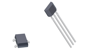
| Typical packages | SOT23 (LH), SIP-3 (UA), SIP-3 with passives (UC) | SOT23 (LH), SIP-3 (UA) |
| Signal path | More complex | Less complex |
| Hall-plate configuration | Single, dual, or more | Single |
| Hall-plate bias | Switched (“chopped”) | Constant |
| Trimming required in Allegro production? |
No | Yes |
| BOP/RP Temperature Stability | Best | Good |
| Stress Resistance | Best | Good |
| Power-On Time | Fast | Fastest |
| Maximum operating frequency | High | Highest |
| Output Repeatability/Jitter | Good | Good |
| fC oscillator? | Yes | No |
| Typical CBYPASS* | 0.1 μF | 0.01 μF |
| Recommended for all applications? | Yes / All | Special situations only |
* Refer to the device datasheet for specific recommendations and guidelines.
Continuous-Time
|
 |
 |
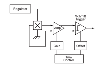
Sensors employing continuous-time operation use only one direction of current flow across the Hall element, and this bias current is constant. This allows the fastest response time between the applied external magnetic field and the electrical output. It is clear how this might be beneficial for applications requiring the fastest output response time.
Magnetic offset changes with environmental conditions and will affect the stability of the Hall switch thresholds (the Operate and Release thresholds, BOP and BRP, respectively). In continuous-time devices, there is no built-in circuitry to remove offsets. This is reflected in the specifications given in the device datasheet: the specified BOP and BRP ranges for a continuous-time device are wider than for a comparable chopper-stabilized device.
Chopper Stabilization
When using Hall-effect technology, a limiting factor for switch point accuracy is the small signal voltage developed across the Hall element(s). This signal voltage is disproportionally small relative to the offsets that can be produced at the output of the Hall element(s). This makes it difficult to accurately process the magnetic signal over the specified operating temperature and voltage ranges.
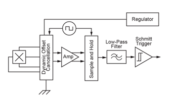
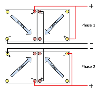
Chopper stabilization is used to minimize offsets in the Hall element(s). The patented Allegro technique, Dynamic Quadrature Offset Cancellation (U.S. Patent No. 5621319, 1997, now expired), removes key sources of output offset and drift induced by thermal and mechanical stresses. This offset stabilization technique is based on a signal modulation/demodulation process. The undesired offset signal is separated from the magnetic-field-induced signal in the frequency domain through modulation. The subsequent demodulation of the magnetic signal acts as a modulation of the offset, causing the magnetic-field-induced signal to recover its original spectrum at baseband while the DC offset becomes a high-frequency signal. The magnetic signal can then pass through a low-pass filter, while the modulated DC offset is suppressed. This signal chain configuration is illustrated in Figure 3. While the signal chain may look more complex than that of the continuous-time device, the Trim Control block is missing, as it is not needed. This leads to savings in chip area and production calibration time. Figure 4 illustrates the alternating Hall element bias that leads to the cancellation of offsets.
In most instances, Allegro’s chopper stabilization employs an 800 kHz clock. For the demodulation process, a sample-and-hold technique is used where the sampling is performed at twice the chopper frequency. This high-frequency operation allows a higher overall sampling rate.
Dynamic Quadrature Offset Cancellation desensitizes the chip to the effects of thermal and mechanical stress and results in extremely stable quiescent Hall output voltages and precise recovery after temperature cycling. Allegro implements this technique in proprietary BiCMOS wafer fabrication processes that support the use of low-offset, low-noise amplifiers in combination with high-density logic and sample-and-hold circuits.
The output’s response time (propagation delay) and time-domain repeatability (jitter) are affected slightly by chopper stabilization. However, the Allegro high-frequency chopping approach minimizes these effects and makes them imperceptible in most applications. Continuously switching the bias current in the Hall
element(s) creates brief, periodic interruptions in the bias current. These perturbations may be observable at the device’s supply pin, resulting in a larger recommended bypass capacitor.
Table 2: Typical Power-On Time, tPO,
B = –50 G, TA = 25°C
| Parameter | Continuous-Time (A1201) |
Chopper-Stabilized (A1220) |
| tPO | 1.94 μs | 10.12 μs |
Performance
The performance data (Table 2) is for example purposes only and was collected using two Allegro digital position sensor ICs, namely the A1220 (chopper-stabilized) and the A1201 (continuous- time).
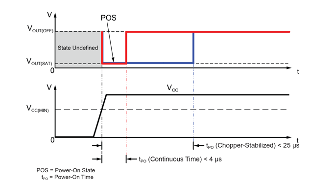
POWER-ON TIME
The power-on time of a digital position sensor is characterized by measuring the time delay between the power supply reaching the minimum specified operating voltage and the output being in a valid state. To generate an output edge in response to the external field, B = BRP(MIN) – 10 G is applied. (Typically, applying a
larger field will cause the observed power-on time to decrease.)
The shorter power-on time of continuous-time devices can be advantageous in applications that rapidly power-cycle the sensor for ultralow power consumption (maximum battery life) or to minimize self-heating. The total time during which the sensor must be powered to produce a valid output is less, resulting in
a lower duty cycle, lower average power consumption, and less self-heating.
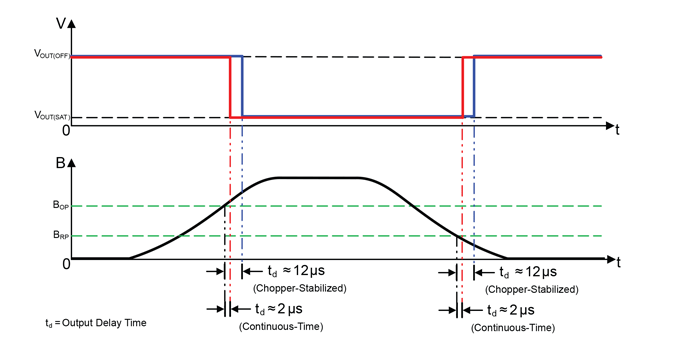
OUTPUT RESPONSE TIME
The response time is measured from the magnetic signal edge to the output edge. The applied magnetic field will propagate through the simpler continuous-time signal path more quickly than the chopper-stabilized device. However, the chopper-stabilized device still responds within 12 μs (See Figure 6).
Table 3: Typical Output Response Time, td,
Ambient Temperature (TA) = 25°C
| Parameter * | Device | Chopper- Stabilized |
Continuous- Time |
| td | –150 G Output Off |
11.4 μs | 2.0 μs |
| 150 G Output On |
9.9 μs | 1.8 μs |
Output response time can become important for applications which operate at very high frequencies. The maximum operating frequency supported is directly related to the output response time, in addition to the signal path bandwidth.
Continuous-time devices typically respond to the magnetic field within 2 μs, enabling operation up to a theoretical 250 kHz (calculated using two output transitions per period). Chopper-stabilized devices have typical response times of 11.4 μs and theoretically support operation up to nearly 44 kHz. While this is a 6:1 advantage for the continuous-time device, the absolute delay times are extremely small in both cases and are not a factor in most practical applications. For both device types, the actual maximum operating frequency is limited by the bandwidth of the signal path.
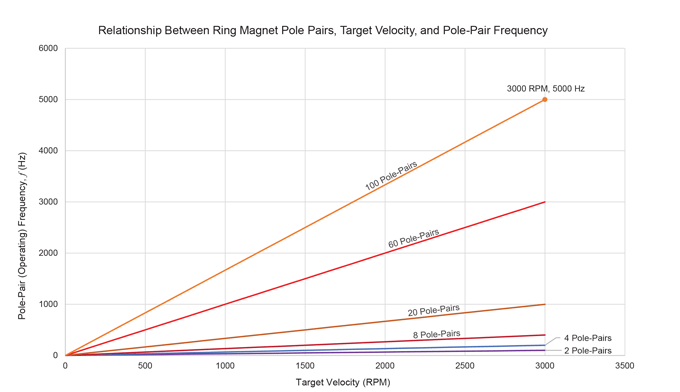
An important relationship exists between ring magnet pole-pair count, target rotation speed, and device operating frequency, f. This relationship is depicted in Figure 7 and expressed in the formula below:
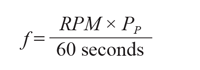
In this expression, the target velocity, RPM, and the target polepair count, PP , determine the effective operating frequency of the Hall-effect sensor.
JITTER
The repeatability (jitter) of a sensor output with respect to a consistent magnetic input signal is determined by the signal-to-noise ratio and the refresh rate (if chopper-stabilized). Continuous-time devices produce a constant Hall signal with very negligible delay. Chopper-stabilized devices require two or more Hall signal samples to take place before the output can be refreshed. This can contribute jitter in the output signal depending on when the magnetic signal transitions relative to the timing of the chopper stabilization phases.
For example, a device with an 800 kHz chopping frequency and 4× chopping (driving current from each of the four corners of the Hall element) will refresh the output state at a rate of:
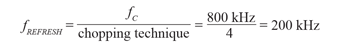
Figure 7 includes several examples of ring magnet pole-pair counts and the resultant magnetic pole-pair frequency. As shown, a high density ring magnet will produce an increased operating frequency for a given target speed. However, all are well within the frequencies which can be measured with Allegro Hall technology.
This 200 kHz rate is equal to a refresh every 5 μs, which, when added to the delay contributed by the remainder of the signal path, can result in a total propagation delay of 6 to 12 μs for a typical chopper-stabilized device.
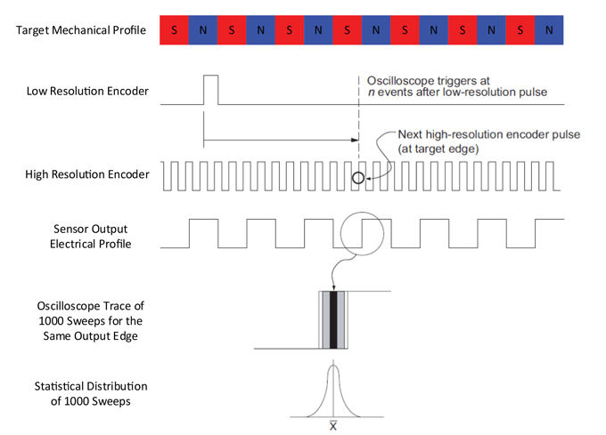
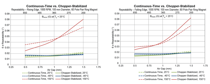
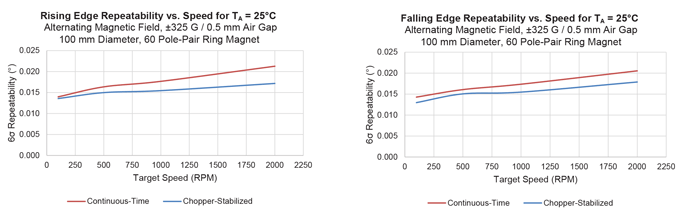
The repeatability versus temperature comparison below (see Figure 9) shows that both sensor types actually exhibit similar performance. The data shown are typical 6-Sigma edge repeatability results using a 60 pole-pair ring magnet with a diameter of 100 mm. BPkPk, shown on the x-axis, represents the magnitude of the magnetic field input. Figure 8 contains an example of the measurement method used to quantify repeatability. When repeatability is measured this way, smaller values indicate better performance, i.e., less jitter. Figure 10 illustrates that the repeatability is very stable with changes in target speed.
Continuous-Time and Chopper-Stabilized Devices
Continuous-Time and Chopper-Stabilized Devices
Temperature has the greatest influence on repeatability. Other contributors include magnetic field strength and consistency as well as target speed. However, the rising and falling edge repeatability for slow speeds is only marginally better than when operating at higher speeds for both the continuous-time and the chopper-stabilized devices.
TEMPERATURE STABILITY
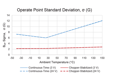 Operate Point Temperature Stability |
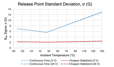 Release Point Temperature Stability |
Chopper-stabilized devices provide an advantage in temperature stability over continuous-time devices. When sensing some magnetic materials, such as ferrite, a drift in magnetic field strength over temperature will occur. Unless one is trying to track the significant temperature drift of a given target, it is ideal for the magnetic switching thresholds to remain constant and within the expected magnetic field input range, for all temperatures.
Better temperature stability is achieved with chopper-stabilized devices. Switch threshold variations are minimized due to the averaging and offset cancellation taking place during chopper stabilization. The data in the adjacent plots (Figure 11 and Figure 12) summarize the standard deviation of the magnetic switch threshold parameters from their typical values for a continuous-time and chopper-stabilized device.
In this example, the standard deviation of the continuous-time devices is typically 3× larger than for the chopper-stabilized devices.
Continuous-time devices are significantly affected by increased temperature, and as a result, the switch threshold variation is up to 5× larger than its chopper-stabilized counterpart. This can result in degraded edge location (timing) accuracy and may require higher magnetic fields from the target and/or a smaller air
gap.
Example standard deviation data for the magnetic switch threshold parameters are shown below (Table 4). Different operating voltages have a negligible effect on the standard deviation.
Table 4: Standard Deviation Switch Threshold Data
| Datasheet Parameter |
Setup | Magnetic Threshold Parameter Standard Deviation, σ (G) | |||||
| TA = –40°C | TA = 25°C | TA = 150°C |
|||||
| Chopper- Stabilized |
Continuous- Time |
Chopper- Stabilized |
Continuous- Time |
Chopper- Stabilized |
Continuous- Time |
||
| Operate Point, BOP |
VCC = 3 V | 2.24 | 7.33 | 2.23 | 6.01 | 2.78 | 12.03 |
| VCC = 24 V | 2.19 | 7.28 | 2.24 | 6.00 | 2.78 | 12.12 | |
| Release Point, BRP |
VCC = 3 V | 2.23 | 6.97 | 2.12 | 5.67 | 2.52 | 12.88 |
| VCC = 24 V | 2.29 | 6.97 | 2.09 | 5.61 | 2.45 | 13.07 | |
| Hysteresis, BHYS |
VCC = 3 V | 1.89 | 2.83 | 2.61 | 2.36 | 1.87 | 2.59 |
| VCC = 24 V | 1.87 | 2.72 | 2.64 | 2.44 | 1.72 | 2.68 | |
Cross-Reference Table
Chopper-stabilized devices are recommended for all applications. The table below should be used as a guide to determine the most suitable chopper-stabilized replacement for a given continuous time device.
Table 5: Continuous-Time to Chopper-Stabilized Cross-Reference
 |
Device Type |
Part Number | BOP (max) | BRP (min) | BHYS | Chopper-Stabilized Replacement |
| Unipolar Switches |
A1101 | 175 | 10 | 80 | A1121 | |
| A1102 | 245 | 60 | 80 | A1122 | ||
| A1103 | 355 | 150 | 80 | A1123 | ||
| A1104 | 450 | 35 | 80 | A1121 or A1128 | ||
| A1106 | 430 | 160 | 140 | A1123 or A1128 | ||
| Bipolar Switches |
A1201 | 50 | -50 | 55 | APS12200 or A1250 | |
| A1202 | 75 | -75 | 150 | APS12200 or APS12210 | ||
| A1203 | 95 | -95 | 190 | APS12210 | ||
| A1205 | 50 | -50 | 55 | APS12200 or A1250 | ||
| Latches | A1210 | 150 | -150 | 300 | A1222 | |
| A1211 | 180 | -180 | 360 | APS12230 | ||
| A1212 | 175 | -175 | 350 | APS12230 | ||
| A1213 | 200 | -200 | 400 | APS12230 | ||
| A1214 | 300 | -300 | 600 | APS12230 |
Summary
Chopper-stabilized devices offer many improvements over continuous-time products. In general, chopper-stabilized devices offer superior temperature stability and stress-resistance (lower switch point drift) and a streamlined production flow versus continuous-time devices. They typically also have the advantage of smaller die size due to the lack of trimming and the use of more modern wafer fabrication processes. There is a small tradeoff in time-domain performance, but this is negligible in most applications.
All of Allegro’s newest products are chopper-stabilized, and chopper-stabilized devices are recommended for all new applications. The slightly faster power-on and incrementally shorter output-delay time of continuous-time devices are generally insignificant. Continuous-time devices remain in production, but are only recommended for special applications, e.g.,
- Applications where the sensor is power-managed by switching its power supply on and off, as continuous-time devices have faster power-on times.
- Extremely high-speed applications that demand the highest operating frequency and absolute lowest jitter/best repeatability, as there is no multiphase chopping action causing additional delay or jitter.
If your applications falls into one of these categories, please consult with your local Allegro field applications engineer to confirm if a continuous-time device is the best choice for your design.