DC and Transient Current Capability/Fuse Characteristics of Surface Mount Current Sensor ICs
By Alex Latham and Scott Milne,
Allegro MicroSystems
Introduction
Allegro MicroSystems offers a broad product family of current sensor IC solutions with integrated conductors. These products can be used to measure current in a variety of applications, including motor control, inverters, load detection and management, and overcurrent fault detection. For applications with normal operating currents up to 80 A, Allegro offers current sensor ICs in a number of standard surface-mount packages, such as SOIC-8, SOICW-16, QSOP-24, and QFN [1]. Due to their integrated conductors, these sensor ICs are placed in series with the current they are measuring. The integrated conductors are especially low resistance (1.2 mΩ down to less than 0.3 mΩ, depending on the package), so they generate very little heat under normal operating conditions. However, like all components that are in the current path, it is important to understand how they behave when subjected to currents above their rated nominal capability due to short circuits, inrush currents, or other transient conditions.
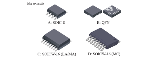
Figure 1: Sensor IC Comparison
Testing Performed and Limitations of Results
The focus of this study was on the SOIC-8, SOICW-16, and QFN-based current sensor ICs Allegro offers. It is important to note that the internal construction of these packages can vary from product to product, even though they use the same generic SOIC-8 or SOICW-16 footprint. Specifically, the packages and associated products tested are shown in Table 1.
| Package | Conductor | Product |
| SOIC-8 | LC1: 1.2 mΩ | ACS711KLC |
| ACS712 | ||
| ACS713 | ||
| ACS714 | ||
| ACS715 | ||
| ACS724LLC | ||
| ACS725LLC | ||
| ACS730KLC | ||
| ACS71240 | ||
| LC2: 0.65 mΩ | ACS722LLC | |
| ACS723LLC | ||
| SOICW-16 | LA: 1 mΩ | ACS710 |
| ACS716 | ||
| ACS720 | ||
| ACS732KLA | ||
| ACS733KLA | ||
| MA: 0.85 mΩ | ACS717 | |
| ACS718 | ||
| ACS722KMA | ||
| ACS723KMA | ||
| ACS724KMA | ||
| ACS725KMA | ||
| ACS732KMA |
||
| ACS733KMA |
||
| ACS71020 | ||
| MC: 0.265 mΩ | ACS724 |
Each package was subjected to the following tests:
| High Current Pulse Behavior (fuse characteristics) |
Time to reach 165°C die temperature vs. current |
| Time to fuse the current conductor open vs. current | |
| DC Current Capability | Die temperature vs. DC current and ambient temperature |
Unless otherwise stated, all data presented here was gathered at room temperature on products that were soldered to the product-specific demonstration boards developed by Allegro2. The heat dissipation characteristics, particularly at moderate currents (<150 A), will vary depending on the PCB layout used for the high current traces near the current sensor IC. Other factors, such as whether or not the PCBA is encapsulated with a conformal coating (i.e., if it is “potted”) and the enclosure that the PCBA is placed into can impact the thermal characteristics of the system. The purpose of this study is to compare and contrast the relative performance of the various product families listed above and give a general idea of what levels and durations of current each package is capable of withstanding. The high current carrying capability of these parts should be verified in the specific application conditions they will be used in.
Test Results
High Current Pulse Behavior (Fuse Characteristics)
There are two different failure modes that can occur when Allegro’s integrated conductor current sensor ICs are exposed to high currents. Depending on the magnitude and duration of the current flowing through the conductor, either or both of the following failure modes can occur:
- The die can be damaged due to heat exposure, which can occur if the die is subjected to temperatures above 165°C.
- The primary conductor will act as a fuse and open.
Figure 2 shows the time vs. current curves of these failure modes for the LC1 package (ACS712/3/4/5 and ACS724/5 devices). The blue curve represents the time until the conductor fuses open, and the black curve represents the time until the die reaches 165°C. At moderate currents (<150 A), these sensor ICs tend to overheat before fusing, which means that the PCB layout and application assembly can have a significant impact on the time to failure at these current levels, as they can help or hinder the flow of heat away from the sensor IC. For higher current transients (>150 A), the sensor ICs tend to fuse open before overheating the die. The time to fuse for these events is mainly dependent on the size and shape of the integrated conductor and will vary less from application to application. Ultimately, one should stay within the Safe Operating Area, below both the fusing and overheating curves, and Figure 3 shows the safe operating region for each of the packages tested.
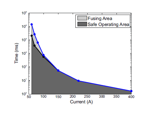
Figure 2: Fuse and Over-temperature Time vs. Current for the LC1 (SOIC-8) Package Type
Besides the failure point, the failure behavior when the sensor IC fuses is also important. In general, when the integrated conductor fuses, the thinnest part of the conductor disintegrates, and the package may crack. In all of the testing performed, when the device fused before overheating, the failure did not result in any shorting between the primary and secondary of the device. However, the isolation rating of the device will be compromised if the package has been damaged.
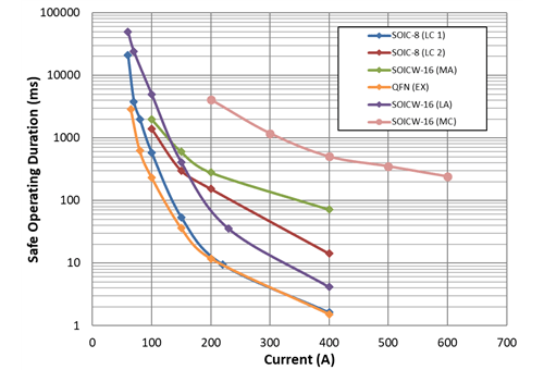
Figure 3: Safe Operating Area - Time for die temperature to reach 165°C or fuse (whichever occurs first) vs. current.
It is also critical to note that if the package is overheated before fusing, the fusing event will be much more energetic. These types of failures occur in the light grey region of Figure 2 (beyond the Safe Operating Area), as that is where one overheats the package before fusing. In those scenarios, significant heat is present, and the response to any overcurrent event in these conditions will be more energetic. Figure 4 shows the time to fuse for each of the packages tested for reference. However, it is important to point out that the part should only be operated in the Safe Operating Region shown in Figures 2 and 3.
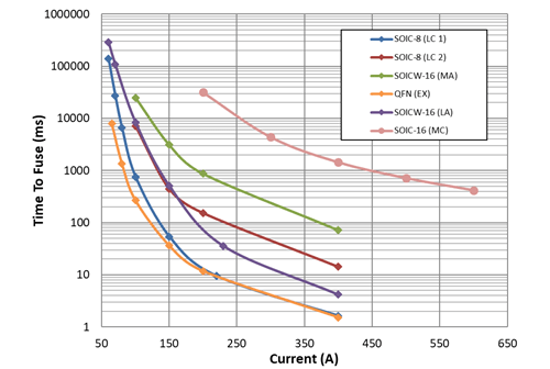
Figure 4: Time to Fuse - Time required for primary conductor to fuse open for vs. current.
DC Current Capability
Similar to the differences in response to high current pulses of various magnitudes and durations, the same physical characteristics of the IC, PCB layout, and application assembly will impact the device’s ability to handle continuous currents and maintain die temperatures below 165°C. The other factor that will impact the part’s ability to safely carry large continuous currents is the ambient temperature. Figure 5 shows the temperature rise of the die vs. DC current for each of the packages tested. This can be added to the ambient temperature in order to determine the absolute die temperature, allowing one to determine the maximum allowable current for a given ambient temperature before the die goes beyond the absolute maximum of 165°C. For example, if the ambient temperature is 45°C and the continuous current through an ACS723LLC (LC2 package) is 50 A, the estimated die temperature inside the package would reach a steady state value of 115°C (45°C ambient temp + 70°C temperature rise).
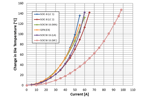
Figure 5: Increase in Die Temperature vs. Current for Each Package Type
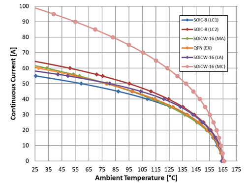
Figure 6: Continuous Current vs. Ambient Temperature for Each Package Type
1For applications that require >50 A, refer to Fifty to Four Hundred Amp Integrated Conductor Sensor ICs for more information.
2Demo board Gerber files are available online in the Frequency Asked questions section of each sensor.