Innovative Back EMF Based Stall Detection Simplifies Stepper Motor Designs
By Dan Jacques, Allegro MicroSystems, LLC
Stepper motors provide significantly more flexibility and control than traditional continuously-rotating electric motors, and they are widely used in a variety of industrial, consumer, and automotive applications. Many applications require reliable detection of reaching a mechanical end point without using an external sensor, and motor stall detection can be used instead. This article describes an innovative method of stepper motor stall detection and its application.
Introduction to Stepper Motors
A general definition for a stepper motor is an electromechanical machine that moves a rotor shaft in small precise increments without feedback to govern motor speed. Stepper motors offer several advantages:
- they exhibit good speed stability when the load fluctuates, because the stepper can maintain constant torque;
- they have good startup characteristics, with maximum torque at zero speed;
- they have wide dynamic ranges and can accelerate faster than servo motors;
- due to the narrowness of the step angle, stepper motors have small mechanical transient responses, which makes position and speed control possible without a complicated control loop.
Thus, the cost of drive solutions for stepper motors is very affordable.
Certain disadvantages occur with steppers; although, advancements in electronics have helped to minimize their effects. Open loop operation fails to provide information about absolute position or whether the motor is responding to input commands. Resonance can cause vibration if motor speed or winding current is not controlled properly. Motors can lose step if the speed is too high.
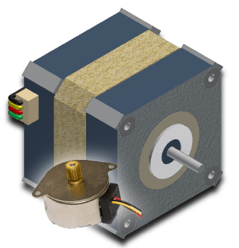
Figure 1: Stepper Motors
Stepper motors come in a variety of sizes and power levels, with many options for precision of stepping performance.
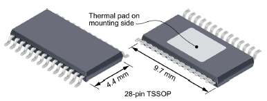
Figure 2: Controller ICs
Full-featured, highly integrated controller ICs are available in industry-standard, low-profile, surface-mount packages with thermal dissipation pads.
Requirement for Stall Detection
In practical systems, a means of stall detection is required to detect when the rotor is stationary, which can be caused by any of several conditions. Rotation of the electrical field generated by the driver may lose synchronicity with mechanical rotation of the stator, or the mechanical load may exceed the design limits of the motor. Any obstruction of the load path, including a fixed mechanical stop, also can cause the motor to stop rotating, but in these instances, without information on absolute position, the motor will attempt to drive through the obstruction in order to ensure that the load reaches the end point. This can cause wear, audible noise, heating, and mechanical failures. In addition, driving a stepper into a fixed stop by design inherently reduces the efficiency of the system, which is critical in battery-operated applications.
To moderate these negative effects, an electronic integrated stall detection function can be used to ensure the load has reached its desired position, or to notify the user if the load is obstructed. When absolute positioning is not required, electronic stall detection can often times replace a costly slip-clutch or optical encoder to provide stall detection. Some common applications requiring this type of stall detection are shown in Figure 3.

Figure 3: Typical Applications Requiring Stall Detection for Stepper Motors
How Stall Detection Works
Electronic stall detection works by measuring the effect of back EMF on the number of PWM cycles. When a motor is stopped or moving slowly, there is little back EMF to impede the current in the phase windings. This allows the current to rise to the limit quickly and the PWM current control to activate. However, when a motor is rotating at normal operating speeds, the back EMF generated by the fields of the magnetic poles passing over the phase windings acts against the supply voltage and reduces the rise time of the phase current. Therefore, the PWM current control takes longer to activate. Assuming a constant step rate, this results in fewer PWM cycles for each step of the motor.
This effect can be seen in Figure 4. Two phases of the winding current are shown and offset so that each step is shown overlaid. Phase B is delayed 90 electrical degrees. This allows direct comparison of the winding current. When phase B current is rising, the motor is still running normally and back EMF acts to limit the current rise time.
The stall is applied at time t = –4 ms. A visual comparison shows that phase A current rises slightly faster causing the device to apply more PWM cycles to control the current. These additional cycles provide the count difference necessary to detect a stall condition. The stall is detected at time t = 0.
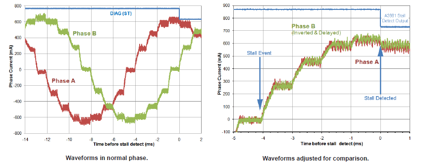
Figure 4: Typical Behavior of Stepper Motors
Method For Determining a Stall
Each motor winding phase has a PWM counter that accumulates the number of current limit events at each full step, from zero to full current. The allowable difference in counts is programmed into the IC onboard diagnostic register. A stall is detected when the count falls below the programmed value.
Phase Limitations of Electronic Stall Detection
There are a few conditions required for electronic stall detection to work properly. Before the stall, the motor must have been stepping fast enough for the back EMF to reduce the phase current slew rate. In addition, the motor cannot be in full step mode, the phase current scheme must conform to 0% and 100% currents at steps 0, 16, 32, and 48, and both phases must have same profile.
Stall Detection Scenarios
There are many factors which can contribute to a stall, so it is important to use an advanced IC that properly evaluates stall signals, such as those shown in Figure 4. In the following figures, two alternative scenarios are presented, and the performance of the Allegro IC detection method is demonstrated.
Hard (Locked) Stall Scenario
A spinning rotor was stopped approximately 2 ms before the stall detect signal indicated a fault by going low. Note how the phase current maintains its shape even though the quantity of PWM cycles has increased (see Figure 5).
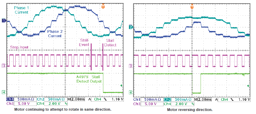
Figure 5: Typical Hard Stall Behavior
Soft (Partial) Stall Scenario
In many cases the rotor stall is not locked, and the rotor vibrates as the drive currents are applied. In these cases it can be difficult to detect a stall as it appears the motor is still moving. The Allegro stepper motor drivers achieve stall detection due to a differential technique used. When a partial stall is applied, the fault output continuously changes state, indicating that the rotor is going in and out of lock (refer to Figure 6).
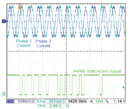
Figure 6: Typical Soft Stall Behavior
Stall Detection Products
The following table summarizes the features of some advanced Allegro devices with stall detection. Additional information about these devices is available on the Allegro website, www.allegromicro. com.
| A3981 | A4979 | A4980 |
|---|---|---|
| SPI compatible or step and direction motion control |
SPI compatible or step and direction motion control |
SPI compatible or step and direction motion control |
| Highly configurable through serial port |
Highly configurable through SPI port | Highly configurable through SPI port |
| 28 V operating supply at 1.4 A output per phase |
50 V supply at 1.5 A output per phase |
50 V supply at 1 A output per phase |
| Overvoltage supply monitor disables outputs when supply exceeds VBBOV |
— |
— |
| Automatic current decay modes with synchronous rectification |
Automatic current decay modes with synchronous rectification |
Automatic current decay modes with synchronous rectification |
| Hot and cold thermal warning and shutdown |
Hot and cold warning and thermal shutdown |
Hot and cold warning and thermal shutdown |
| Undervoltage lockout | Undervoltage lockout | Undervoltage lockout |
| Open load stall detect features and shorted load detection |
Open load stall detect features and shorted load detection |
Open load stall detect features and shorted load detection |
| Small, 28-lead thermally enhanced package | Small, 28-lead thermally enhanced package | Small, 28-lead thermally enhanced package |
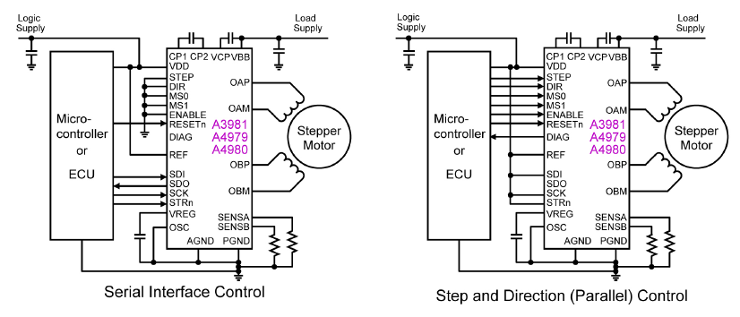
| Control interfaces (see figure 7): Serial Port or SPI bus Step and Direction (parallel) |
Control Interfaces (see figure 7): Serial Port or SPI bus Step and Direction (Parallel) |
Control Interfaces (see figure 7): Serial Port or SPI bus Step and Direction (Parallel) |
| K (–40°C to 125°C) ambient operating temperature range |
G (–40°C to 105°C) ambient operating temperature range |
K (–40°C to 125°C) ambient operating temperature range |
| AEC-Q100 qualified |
— |
— |