Programming a Back Biased Switch for Proximity Sensing
Proximity Sensing Programming Technique
Proximity Sensing
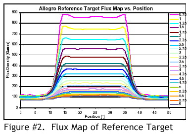
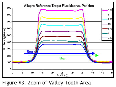
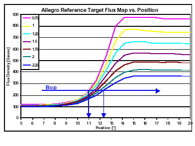
In the proximity sensing case the switchpoint is programmed to achieve the desired position, which may be in millimeters or degrees on the horizontal axis of figures #2, 3, and 4. Programming makes it possible to compensate for mechanical offsets generated during manufacturing, which allows for tight control of the switching position. For example: if the desired switchpoint in figure #4 is 12° and the device is installed at 0.75mm air gap, then BOP in should be programmed at approximately 400 Gauss, a higher level than that shown in the figure. If the device were installed at 2.25mm air gap then BOP should be programmed at just over 200 Gauss or slightly lower than that shown in figure #4.
Note: care must be taken not to adjust the switch-point too close to either the tooth or the valley field as the IC switch-point will vary over temperature according to the specification. If the switching threshold drifts above the tooth signal or below the valley signal at any given installation air gap then the device will not switch.
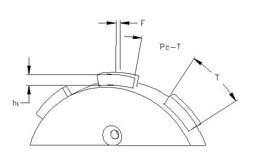
Reference Target Dimensions
| Target | Diameter (Do) |
Thickness (F) |
Tooth Width (T) |
Valley Width (Pc - T) |
Valley Depth (ht) |
|---|---|---|---|---|---|
| Reference Target | 120mm | 6mm | 23.5mm | 23.5mm | 5mm |
Gear Parameters for Correct Operation
| Characteristic | Description | Limits | |||
|---|---|---|---|---|---|
| Min. | Typ. | Max. | Units | ||
| Valley Depth (ht) | Depth of Target Valley | 5 | — | — | mm |
| Valley Width (Pc - T) | Length and Width of Target Valley | 30 | — | — | mm |
| Tooth Width (T) | Width of Target Tooth | 5 | — | — | mm |
| Thickness (F) | Thickness or Length of Target Tooth | 5 | — | — | mm |
Possible Applications
- Proximity sensing
- Vane interrupter switch
- Speed sensing
- Cam sensing
- Rotary Encoder
- Brake light switch
- Revolution counting
- Flow meter
- Level meter
- Non-contact limit switch
- Brushless motor commutation
- Headlight position sensing
Please visit the Allegro website, www.allegromicro.com, for magnet suppliers.
Reference STP99-2