DC Current Capability and Fuse Characteristics of Current Sensor ICs with 50 to 200 A Measurement Capability
Introduction
Allegro Microsystems offers a wide range of current sensor IC solutions that fall into two main categories: ICs having an integrated current-carrying conductor and ICs designed to be used with an external magnetic core. Of the current sensor ICs with integrated current-carrying conductors, there are two packages that can be used to measure currents from 50 to 200 A [1]: the LR and the CB. Because of the integrated current-carrying conductor, these ICs are placed in series with the current to be measured. To reduce power dissipation on the integrated conductors, the resistance is very low (200 μΩ for the LR package and 100 μΩ for the CB package). It is still important to know the thermal performance of these ICs when they are subjected to DC currents, short circuits, inrush currents, or any other fault condition. In this way, designers can design PCB layouts and protection features to optimize current sensor performance and to understand the boundary conditions in the application.
Background
Both the CB (Figure 1) and LR (Figure 2) packages are evaluated in this application note. Several devices are offered in these packages, as shown in Table 1 and found on the Allegro website (click device numbers below for more information).
Table 1: Devices and Package Offerings
| Package | Device |
| LR | ACS780 |
| ACS781 | |
| CB | ACS758 |
| ACS759 | |
| ACS770 |
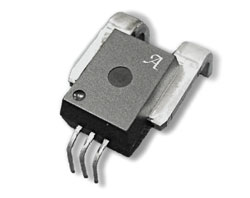 Figure 1: CB Package
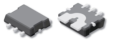 Figure 2: LR Package
Tests Performed
Thermal performance of Allegro current sensor ICs is subjected to two types of tests: high-current transient pulse tests and DC constant-current tests. In the first tests, the package is subjected to a current pulse of a set magnitude and the time is measured for two boundary conditions: the time for the die temperature to go above the maximum junction temperature (165°C), and the time to fuse the current conductor open. In the second tests, the package is subjected to a constant DC current and the steady-state die temperature increase is recorded.
Note these tests are dependent on the printed circuit board design. For all of the tests performed in this application note, the devices were soldered to the standard Allegro evaluation board [2] (Figure 3 and Figure 4). The heat dissipation properties of a circuit board will vary based on PCB layout as well as the influence of other nearby devices. This is especially true for currents less than 150 A. The goal of these tests is to provide a general guide of the thermal performance of devices tested. The thermal performance of each package should be verified in the specific application in which it is to be used. Allegro demo board thermal performance can be easily achieved by following a few basic layout guidelines described below.
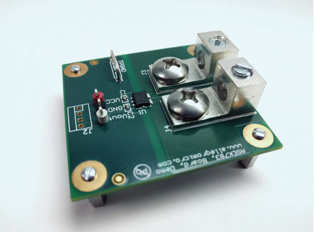 Figure 3: LR Evaluation Board
 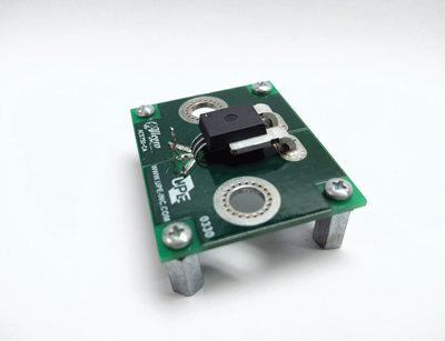 Figure 4: CB Evaluation Board
Layout Guidelines for Thermal Performance
When laying out a PCB for an Allegro current sensor IC, there are a few key elements that will help with thermal performance. These include: dense thermal vias surrounding the solder pad locations, multiple layers of metal directly under the current path to help spread the heat, and locating any heat sinking elements as close to the device as possible (refer to Figure 5). The evaluation boards used are each 8 layer boards of typical 2-ounce copper. In general, greater than 2-ounce copper layers are not needed as long as the layout of the PCB is done with care and with thermal performance in mind.
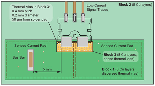 Figure 5: PCB Layout Example – LR Package
High-Current Pulse Testing
High-current pulse testing for LR and CB package were performed at multiple peak current levels. All data was taken at 25°C ambient temperature. Only the results for the LR package are shown in Figure 6, as the maximum current capability of the lab equipment was only 700 A, and that was not enough to cause any fusing of the CB package.
Referencing Figure 6, the green area is the safe operating area (this means that the maximum junction temperature was not exceeded). The orange area shows the area in which the maximum junction temperature has been exceeded, but the current conductor has not yet fused open. The results from the high current pulse testing on the LR package show that at 300 A, it takes more than 2 seconds for the maximum junction temperature to be exceeded. At 675 A, the fuse point and the point at which the maximum junction temperature is exceeded occur at nearly the same time, at about 100 ms.
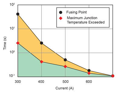 Figure 6: LR Package – Fuse and Overtemperature Time as a Function of Applied DC Current
DC Current Capability
DC current capability tests were performed on both the LR and the CB package. The results are shown in Figure 7. The results from both packages show an impressive current capacity. The CB package shows more capacity than the LR package; however, the LR package is much smaller and has double the resistance through the current-carrying conductor, so this is to be expected.
For the LR package, at 50 ADC, there is an increase of only 20°C. With the CB package, at 100 ADC, there is an only an increase of 20°C. This data is taken at 25°C ambient temperature, but can be used to derate the sensors at any operating temperature.
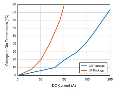 Figure 7: Die Temperature Increase as a Function of DC Current Applied
Conclusion
The test results in this application note show the impressive thermal characteristics of the LR and CB packages. The LR package can handle a great deal of current, especially considering its small footprint of only 6.4 mm × 6.4 mm × 1.5 mm. The CB package, a much larger package, has a very impressive current capacity— able to handle 200 ADC with only ~85°C temperature increase. The data contained within this application note can be used as a guide when designing-in Allegro current sensor ICs and to derate the continuous current for applications over the application operating temperature range. Visit the Allegro current sensor landing page.
1 For applications that require < 50 A, refer to /en/insights-and-innovations/technical-documents/hall-effect-sensor-ic-publications/dc-and-transient-current-capability-fuse-characteristics for more information.
2 Demo board Gerber files are available for each sensor.