Common Mode Field Rejection in Coreless Hall-Effect Current Sensor ICs
Background
Allegro current sensor ICs use the Hall-effect to measure the magnetic field produced by an integrated, current carrying loop, translating the magnetic field to a voltage which is proportional to the current flow. This technology has many advantages, including galvanic isolation, low power loss, and high accuracy over temperature. This technology also has near zero magnetic hysteresis, as there is no core used for concentrating the field. However, the disadvantage of not using a core is that the sensor IC is susceptible to stray magnetic fields. With a core, stray magnetic fields are shunted around the sensor IC, as the core provides a low reluctance path around the sensor IC. Without the core, stray fields from high current carrying traces or solenoids, for example, will be seen by the Hall plate and may result in error in the current measurement. Proper board and system design can avoid these sources of error in the current measurement; however, optimized trace layout can undesirably constrain the PCB and system design. The solution to this issue is integrated differential current sensing.
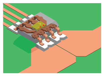
Figure 1: ACS724 Integrated Current Sensor IC
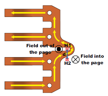
Figure 2: Integrated Current Sensor IC Leadframe with Differential Hall Plate Configuration
Differential Current Sensing Theory
The basic principle behind differential current sensing is that the fields produced on either side of a current carrying conductor are opposite in polarity. This means that when using a current carrying lead-frame as shown in Figure 2, Hall plate 1 (H1) will see a field out of the page, and Hall plate 2 (H2) will see a field into the page for the current flow shown. When there is a common field on the current sensor IC, both Hall plates will see the same field. By subtracting the outputs of the two Hall plates, one is able to reject these externally produced fields. The output of the differential current sensor IC will be:
![]()
Here, B1 is the field seen by H1, B2 is the field seen by H2, and G is the gain of the sensor IC in mV/Gauss. If there is a current flowing through the lead-frame (I) and a common mode field on the sensor IC (BC), then the output of the differential sensor IC will be:
![]()
Here, C1 is the coupling factor for H1 in Gauss/Amp, and C2 is the coupling factor for H2 in Gauss/Amp. Simplifying this equation results in:
![]()
The common mode field (BC) is cancelled out, and the output signal is only proportional to the current flowing through the sensor IC. Also, as Hall plates only measure fields in one dimension, external fields in any other plane will be ignored by the sensor IC.
Limiting Factors in Differential Current Sensing
There are two main limitations to the rejection capabilities of differential current sensing:
- Hall plate matching: Any mismatch in the two Hall plates will result in some change in the output of the differential sensor IC due to common mode fields. Allegro current sensor ICs are monolithic devices, so both Hall plates are on the same silicon, resulting in high levels of matching both nominally and over temperature. Hall plate matching on a single die is normally better than 1%.
- Field Gradients: If the external, interfering field is not uniform across both Hall plates, the difference in the interfering field will propagate to the output of the sensor IC. This limitation is addressed by placing the two Hall plates as close together as possible while still being on opposite sides of the conductor.
Common Mode Rejection for Uniform External Fields
Typical Hall plate matching on silicon is around 1%, which limits the rejection of common mode fields to around 40 dB. The error in Amperes on the output of the sensor IC due to this uniform external field (BC) will be:
![]()
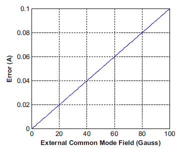
Figure 3: Error (in Amperes) vs. Common Mode Field Due to 1% Mismatch in the Two Hall Plates. Cf = 10 G/A
Here CF is the coupling factor in Gauss/Ampere of the current flow through the sensor IC to the Hall plate, which is equal to C1 + C2 above. Most Allegro integrated current sensor ICs have a coupling factor of around 10 to 15 G/A, which results in the output error (in amperes) vs. external field in Figure 3. To give an idea of what it takes to produce these types of fields, 50 A flowing in a wire only 10 mm away from the sensor IC produces 10 Gauss on the sensor IC. With 1% Hall plate matching, one would only see around 10 mA of error on the output of the sensor IC due to this field compared to 1 A of error without common mode field rejection.
Common Mode Rejection for Fields from Nearby Current Carrying Conductors
One of the most common interfering fields in current sensor IC applications is nearby current carrying conductors. These could be other phases or ground return paths, for example. The issue with fields due to current carrying conductors is that they can produce non-uniform fields on the two Hall plates, depending on the orientation of the current flow. The worst case is when the current flow is perpendicular to the two Hall plates, which is shown in Figure 4.
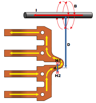
Figure 4: External Current Flow Perpendicular to the Two Hall Plates
In this case, the fields seen by H1 and H2 are:
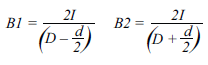
Here, I is in amperes, D is in mm, d is in mm, and B1 and B2 are in Gauss. When using only one Hall plate, B1 is the field which will be seen. When using a differential configuration, the fields from the two Hall plates (B1 and B2) are subtracted, resulting in:
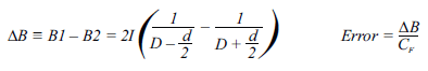
Dividing these fields by the coupling factor, CF (~10 to 15 G/A), converts these interfering fields to error in amperes. Figure 5 shows the error versus distance when only using one Hall plate,
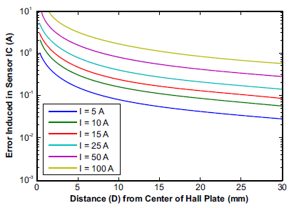
Figure 5: Error (A) vs. Distance from Current Carrying Wire for Single Hall Sensing (d is 0.8 mm)
Figure 6: Error (A) vs. Distance from Current Carrying Wire for Differential Sensing with Current Flowing Perpendicular to Hall Plates (d is 0.8 mm)
and Figure 6 shows the error when using the differential configuration. Then, Figure 7 shows the rejection ratio (in dB) between the single Hall and differential Hall configurations. The notable points are -20 dB where the rejection is 10X and -30 dB where the rejection is 30X. These points will depend on the ratio of D to d, as is shown in Figure 8. Figure 8 remains the same for all D and d values, meaning reducing the distance between the Hall plates and increasing the distance from the Hall plates to the external current carrying wire will always reduce the amount of error in the measurement. Most Allegro integrated current sensor ICs have Hall spacing (d) around 0.6 to 1 mm.
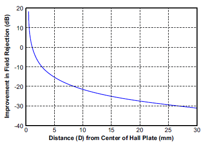
Figure 7: Rejection Ratio of Single Hall vs. Differential Hall Configuration Over the Distance of the External Wire from the Sensor IC. The external wire has current flowing perpendicular to the two Hall plates. d is 0.8 mm.
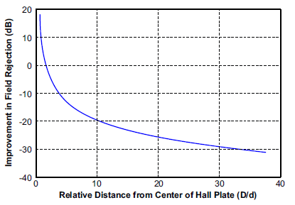
Figure 8: Rejection Ratio of Single Hall vs. Differential Hall Configuration Over the Relative Distance of the External Wire from the Sensor IC (D/d) The external wire has current flowing perpendicular to the two Hall plates.
When the nearby current carrying conductor has current flowing parallel to the two Hall plates, this results in equal fields on both Hall plates. This is the ideal case where the theoretical rejection is infinite. Here, the limiting factor in rejection is the matching of the Hall plates, as mentioned above. Of course, there are all the cases in between the worst case perpendicular configuration and best case parallel configuration. This is illustrated in Figure 9, and the interfering field can be calculated as:
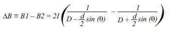
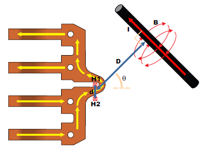
Figure 9: Off Angle Field from a Nearby Current
Experimental Data
The ACS724 current sensor IC, which makes use of differential current sensing, was used to validate the analysis presented here. The test was performed by placing a high current carrying wire next to the sensor IC, perpendicular to the Hall plates, and measuring the change in the sensor IC output at different distances and current levels. In order to estimate the error, the key parameters for the ACS724 are:
- The distance between the Hall plates (d) is 0.7 mm.
- The coupling to one Hall plate is 11 G/A, and the coupling to the other Hall plate is 2.8 G/A, so the total coupling factor (CF) is 13.8 G/A.
This means that the estimated error in Amperes is:
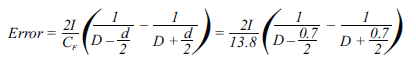
Figure 10 shows dashed lines for the estimated error using this equation, and the dots on the plot represent measured values. Overall, the experimental data matches relatively closely with the calculated error. The measured error is likely slightly lower than the calculated error due to the nearby wire not being perfectly in plane with the Hall plates, resulting in reduced field on the sensor ICs.
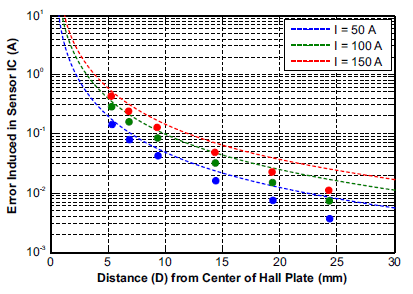
Figure 10: Estimated Error (A) vs. Distance from Current Carrying Wire for Differential Sensing
Conclusion
Ultimately, integrated differential current sensing provides one to two orders of magnitude reduction in error due to stray magnetic fields. This allows the user of these sensor ICs to worry less about stray fields interfering with the current measurements, simplifying PCB layout, and allowing for more physically compressed systems. For highly compressed systems where there are high current carrying traces or magnetic generating devices, such as solenoids, the analysis provided in this application note can be used for quickly estimating the amount of error due to these stray fields. This allows the designer to foresee and correct for system configurations or PCB layouts which will introduce too much error into the system, reducing the number of design iterations.
H2 { PADDING-BOTTOM: 10px }