Two Wheeler Stop/Tail LED Driver
Abstract
In two-wheeler stop and tail light applications, particularly those that use a Rear Combination Lamp (RCL), OEMs use LEDs instead of incandescent bulbs to ensure longer application life. Existing stop and tail light applications use LED drivers and mechanical switches for the brake and tail switches. However, mechanical switches are subject to damage and deterioration over time. Allegro MicroSystems has developed the APS13568, a unique device that combines an LED driver and a Hall-effect switch in a single-chip solution. The APS13568 provides reliability and ease of design of RCL application with minimum external components.
The APS13568 provides a non-contact switch and an external control input to control LEDs.
Introduction
In two-wheeler applications, an RCL is used to illuminate as both a tail light and a brake light. In tail mode, the LEDs are dimmed with lower current, and when braking, the LEDs operate at full brightness with higher current.
This application note describes the use of the APS13568 LED driver with Hall-effect switch and the A6261 LED driver integrated circuit (IC) from Allegro MicroSystems for automotive two-wheeler RCL applications.
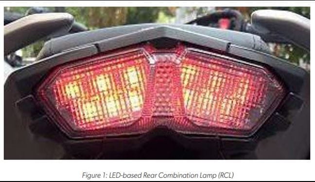
A typical LED based RCL is shown in Figure 1.
Typical two-wheeler RCL specifications are:
1. Operating supply voltage: 8 to 18 V and load-dump spec as ISO7637.
2. Reverse-battery protection.
3. Two or three red LEDs in series, multiple strings connected in parallel for bigger lamps. Maximum output voltage 4 to 6 V.
4. LED current in brake mode: 150 to 300 mA; tail mode is typically 25-50% of brake mode.
5. Two brake inputs and a tail input.
Single-String RCL Using APS13568 LED Driver
Allegro MicroSystems’ APS13568 LED driver combines an ultrasensitive, omnipolar, micropower Hall-effect switch with a linear programmable LED driver. The IC provides reliability and ease of design for RCL applications with minimum external components.
Features and Benefits of APS13568
• Integrated linear LED driver and Hall-effect switch.
• Micropower (25 μA, typical) when LED is off.
• Ultra-sensitive and omnipolar operation for use with lowcost magnets and orientation-independent placement.
• Hall-effect switch output and LED driver enable pins support external logic building.
• Linear, low-dropout LED drive up to 150 mA
□ Set by external reference resistor
□ Short-to-ground and thermal protection
□ Adjustable duration for fade-in and fade-out set with external capacitor
Application Circuit
A typical RCL application using an APS13568 is shown in Figure 2. This controller is placed below the brake pedal switch. The brake pedal position is sensed by an internal non-contact Hall sensor. Handbrake and tail switch inputs are connected as external input signals to the driver.
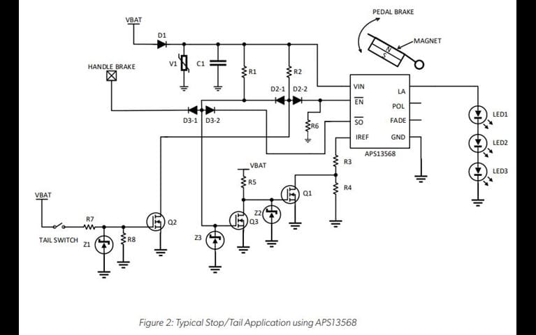
Circuit Description
The supply voltage to the IC is provided by the 12 V battery through diode D1. Diode D1 provides reverse-battery protection. Varistor V1 protects the IC from voltage transients and load dump. Capacitor C1 is a bypass capacitor placed close to the IC. The FADE pin is intentionally kept open, because in this application, the LED must glow instantly when the brake is applied. POL is kept open to turn on LEDs when the magnet moves close to the APS13568 IC. If the driver is placed such that the distance between the LED driver and magnet increases when brake is applied, connect POL low. The LEDs current is switched between high current and low current for brake or tail function.
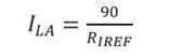
The current through the LEDs is set by a resistor connected to the IREF pin (R3 and R4). LED current is given by:
where ILA is in amps, RIREF is in ohms (R3 + R4). The temperature monitor function available in the APS13568 reduces the LED current as the silicon junction temperature increases above 130°C. As the junction temperature of the APS13568 increases, the regulated current level is reduced, reducing the dissipated power in the APS13568 and in the LEDs. Above 130°C temperature, the current will continue to reduce at a lower rate until the temperature reaches the overtemperature shutdown threshold temperature (165°C). If the chip temperature exceeds the overtemperature limit, the driver will be disabled. The temperature will continue to be monitored and the regulator will reactivate when the temperature drops below the threshold.
Light Operation
Two-wheeler tail lights operate as follows: when the tail switch is closed, the Q2 MOSFET turns on. MOSFET Q2 pulls the EN pin low to enable the IC. Resistors R3 + R4 are connected between the IREF pin to GND pin to set lower LED current. Brake lights illuminate via input from either the brake pedal or handbrake, which utilize different methods of triggering operation as follows:
Brake Pedal-Based Operation
A magnet is attached to the brake pedal and the IC is placed perpendicular to the magnet. When the brake is applied, the magnet moves closer to the sensor, applying stronger magnetic field that pulls the SO pin low. This pulls the EN pin to low through diodes D2 and D3-2. MOSFET Q3 turns off and MOSFET Q1 turns on. Resistor R3 sets higher current for brake application. When the brake is released, the magnet moves away and the SO pin goes high. This pulls the EN pin high to disable the driver.
Handbrake-Based Operation
The handbrake signal is provided either through a mechanical switch or through an omnipolar Hall-effect switch (A1126 or similar). This logic input should be active-low input. When the brake is applied, this input is pulled low, which pulls down the EN pin through diodes D2 and D3-1 to enable the driver. This also turns MOSFET Q3 off and MOSFET Q1 on.
Resistor R3 sets higher current for the brake application. When the brake released, the EN pin is pulled high to disable the driver.
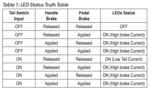
The status of LEDs after brake and tail inputs are applied to the LED driver is described in Table 1:
A printed circuit board for the APS13568 IC is shown in Figure 3.
VBAT = Battery Voltage Input, BRAKE= Brake Pedal Input, TAIL = Tail Input, LEDs connected between LA and GND pin.
LED current is switched between low current and high current as the tail or brake input is applied as shown in Figure 4.
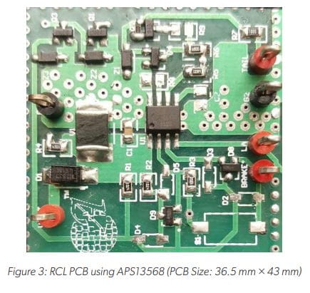
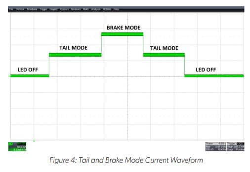
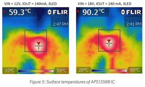
Figure 5 shows the surface temperature of the APS13568 at 12 V and 18 V supply voltages with three red LEDs in series for 140 mA continuous current at 25°C ambient temperature.
Magnet Selection
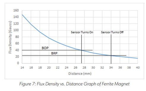
The magnet selection depends on the BOP levels of the APS13568 and air gap requirement.
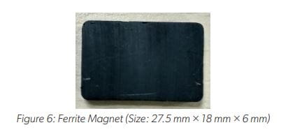
The Hall-effect switch operates either a north or south magnetic pole. This simplifies production as magnet placement need not be polarity-specific. For this application, a low-cost ferrite magnet can be used. The magnet should be placed parallel to the IC such that the magnetic field produced by the magnet is perpendicular to the IC.
A larger magnet should be used to cover the IC surface when the pedal moves; 27.5 mm × 18 mm × 6 mm is recommended for this application. With a ferrite magnet as shown in Figure 6, the APS13568 magnetic switch turns on at 27.3 mm (BOP = 40 G) and turns off at 34 mm (BRP = 25 G) as shown in Figure 7.
On-Board Protections
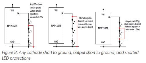
On-board protection for short-to-ground faults and thermal overload prevents damage to the APS13568 and LED string by limiting the regulated current until the short is removed and/or the chip temperature has reduced below the thermal threshold. Figure 8 shows the different fault protections (any cathode short-to-ground, output short-to-ground, and shorted LED) of the APS13568 IC. The IC returns to normal operation when the fault is removed.
Multistring RCL Application Using A6261 LED Driver
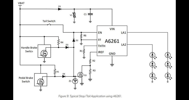
The APS13568 must be placed at the brake pedal when used in stop/tail light applications and supports only a single LED string. If there is any brake pedal placement limitation for the APS13568 PCB due to size constraint, or if there is a requirement for more LED strings or higher current for larger RCL, Allegro also provides linear programmable LED drivers for automotive stop/tail alight pplication. The typical application circuit of the A6261 for automotive stop/tail light application is shown in Figure 9 and printed circuit board Figure 10.
The LED current switches between high and low current for stop/tail light applications when particular stop or tail input is applied to the enable pin of the IC. The LED current is set by using the IREF pin through R2 and R3 resistors. It is possible to use a mechanical switch for tail/stop input or non-contact type Hall-effect sensor as per requirement.
Application Circuit Description
The supply voltage to the IC is provided by a 12 V battery through diode D1. Diode D1 provides reverse-battery protection. When the brake applied, the EN pin is pulled high to enable the A6261 LED driver. This also turns on MOSFET Q1 and resistor R2 sets higher current through the IREF pin. When the brake released, the EN pin is pulled down to disable the driver.
When the tail switch is applied, the EN pin is pulled high to enable the driver, which turns on the LEDs with lower current. Lower current is set by R2 and R3 resistors connected between the IREF and GND pins. The on-board protections of the A6261 LED driver are similar to the APS13568 as mentioned in Figure 8. In addition, the A6261 disables all LEDs on detection of a single open LED condition.
The THTH pin sets the thermal monitor threshold, TJM, where the output current starts to reduce with increasing temperature. Thermal monitor activation temperature can be set to a desired level by setting the voltage on the THTH pin.
A resistor connected between THTH and GND will reduce VTHTH and increase TJM. Connecting THTH directly to GND will disable the thermal monitor function.
The supply input is applied between the VBAT and GND pins, and the LEDs are connected between the LA1, LA2, and GND pins.
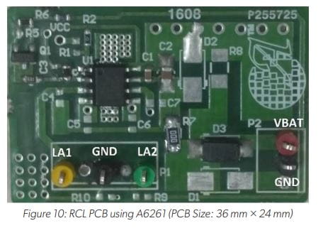
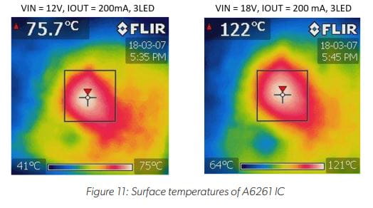
Figure 11 shows the surface temperature of the A6261 at 12 V and 18 V supply voltages with three red LEDs in series for 200 mA continuous current at 25°C ambient temperature.
Conclusion
The APS13568 offers a uniquely designed solution capable of both detecting pedal travel, as well as driving illumination. Rather than requiring multiple discrete components, the single-chip design of the APS13568 for a single-channel RCL provides a more durable component, reducing the possibility of damage and deterioration. The single IC design makes the APS13568 an ideal choice for designers looking to save design time, board space, and cost. Also available is the A6261 LED Driver for applications requiring both a higher current and number of LEDs.
Copyright 2020, Allegro MicroSystems.
The information contained in this document does not constitute any representation, warranty, assurance, guaranty, or inducement by Allegro to the customer with respect to the subject matter of this document. The information being provided does not guarantee that a process based on this information will be reliable, or that Allegro has explored all of the possible failure modes. It is the customer’s responsibility to do sufficient qualification testing of the final product to insure that it is reliable and meets all design requirements.
Copies of this document are considered uncontrolled documents.