Advanced Power Management Using the ALS31300 and ALS31313 3D Hall-Effect Sensor ICs with I2C Output
By Wade Bussing,
Allegro MicroSystems, LLC
Abstract
With the proliferation of human interface devices, there is a growing need for robust, non-contact sensing solutions that are low cost, low power, and low form factor. The Allegro ALS31300 and ALS31313 3D Hall-Effect Sensor ICs in small DFN10 package are ideally suited for trigger, push button, rotation, joystick, and 2D slider joystick applications. The highly configurable power management options, including low power duty cycle mode, sleep mode and wake on motion, make these devices well-suited in battery-powered applications such as drones, camera gimbals, as well as console and mobile gaming controllers. This application note discusses the unique and advanced low power modes available on the ALS31300 and ALS31313 3D Linear Hall-Effect Sensor ICs with I2C output available from Allegro MicroSystems.
References throughout this application note to the ALS31300 also apply for the ALS31313, except that the ALS31300 is provided in a 10-contact DFN package, and the ALS31313 is provided in a TSSOP-8 package.
Introduction
The ALS31300 is a 3D linear Hall-effect sensor IC from Allegro MicroSystems. The ability to sense magnetic fields in three different axes allows the ALS31300 to be extremely versatile to sense linear motion on any axis or rotational motion using magnetic data from two axes. This application note will walk the user through application examples and device configuration tailored for specific application needs.
The ALS31300 sensor may operate on supply voltages from 2.65 to 3.5 V and features highly configurable power management to maximize efficiency. The available power modes and typical supply currents for the ALS31300 are listed in Table 1.
Table 1: ALS31300 Power Modes
| Operating Mode | Mode Description | Suppy Current (Typical) |
| Active Mode | The device continuously updates magnetic and temperature data. Supply current is constant. |
ICC(ACTIVE) ≈ 3.4 mA |
| Sleep Mode | The device is in a near powered-off state. No magnetic or temperature data updates. Supply current is constant. |
ICC(SLEEP)≈ 14 nA |
| Low Power Duty Cycle Mode (LPDCM) |
The device toggles between fully active and inactive state. The device periodically wakes up to refresh magnetic and temperature data. |
ICC(ACTIVE)≈ 3.4 mA ICC(INACTIVE)≈ 12 μA |
The operating mode of the ALS31300 is determined by the value in the Sleep field: address 0x27, bits 1:0. These bits may be accessed at any time and are described in Table 2.
Table 2: Sleep Register
| Address | Bits | Value | Operating Mode |
| 0x27 | 1:0 | 0 | Active Mode |
| 1 | Sleep Mode | ||
| 2 | Low-Power Duty Cycle Mode (LPDCM) |
Sleep Mode
In sleep mode, the ALS31300 is in a near powered-off state where it consumes the minimum amount of current (14 nA, typical). In this mode, the device will still respond to I2C commands, but will not update magnetic or temperature data. Sleep mode is valuable in applications where the supply voltage cannot be disabled but minimal power consumption is required. The time it takes to exit sleep mode is equivalent to Power-On Delay time (tPOD).
Low Power Duty Cycle Mode (LPDCM)
In Low Power Duty Cycle Mode (LPDCM), the ALS31300 toggles between active and inactive states, reducing overall current consumption. The average ICC for the ALS31300 during low power duty cycle mode varies based on the settings used, and may range between 12 μA to 2 mA (typical).
The diagram in Figure 1 shows the profile of ICC as the ALS31300 toggles between active and inactive states during Low Power Duty Cycle Mode.
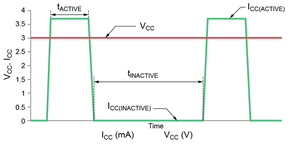
The duration tINACTIVE is determined by the field Low Power Mode Count Max: address 0x27, bits 6:4. The ALS31300 offers eight discrete time frames for tINACTIVE. The typical values for tINACTIVE are listed in Table 3. Typical ICC during tINACTIVE ≈ 12 μA.
Table 3: LPDCM Inactive Time (tINACTVE)
| Address | Bits | Value | tINACTIVE (typ) (ms) |
| 0x27 | 6:4 | 0 | 0.5 |
| 1 | 1 | ||
| 2 | 5 | ||
| 3 | 10 | ||
| 4 | 50 | ||
| 5 | 100 | ||
| 6 | 500 | ||
| 7 | 1000 |
The duration of tACTIVE, shown in Figure 1, is dependent on two settings: BW Select and the number of active channels.
Magnetic sensing channels on the ALS31300 are enabled independently by writing ‘1’ to the channel x en, channel y en, and channel z en bits, listed in Table 4.
Table 4: Channel Enable Control
| Address | Bits | Value | Description |
| 0x02 | 8 | 1 | Enables Z Sensing Channel |
| 7 | 1 | Enables Y Sensing Channel | |
| 6 | 1 | Enables X Sensing Channel |
BW Select controls the amount of filtering applied to the sampled magnetic data. Values for BW Select and corresponding update rates (typical) are listed in Table 5.
Table 5: BW Select and Update Rate
| BW Select Value |
1 Channel Update Rate |
2 Channel Update Rate |
3 Channel Update Rate |
–3 dB Bandwidth |
|||
| μs |
kHz | μs | kHz | μs | kHz | kHz | |
| 0 | 160 | 6 | 330 | 3 | 495 | 2 | 3.5 |
| 1 | 80 | 13 | 170 | 6 | 255 | 4 | 7 |
| 2 | 40 | 25 | 90 | 11 | 135 | 7 | 14 |
| 3 | – | – | – | – | – | – | – |
| 4 | 64 | 16 | 138 | 7 | 207 | 5 | 10 |
| 5 | 32 | 31 | 74 | 14 | 111 | 9 | 20 |
| 6 | 16 | 63 | 42 | 24 | 63 | 16 | 40 |
| 7 | – | – | – | – | – | – | – |
Resulting noise performance for each BW Select value is listed in Table 6.
Table 6: BW Select, Filtering Modes and Resulting Noise Performance (Input Referred)
| BW Select Value |
FIR Enabled | Z Channel Noise (G) |
X/Y Channel Noise (G) |
| 0 | 1 | 1.5 | 4 |
| 1 | 1 | 2 | 5 |
| 2 | 1 | 2.2 | 7 |
| 3 | – | – | – |
| 4 | 0 | 2 | 6 |
| 5 | 0 | 2.5 | 8 |
| 6 | 0 | 3.5 | 10 |
| 7 | – | – | – |
Configuring Low Power Duty Cycle Mode
This section will serve as a guide for configuring Low Power Duty Cycle Mode (LPDCM) based on a few top-level system requirements. Users should consider the goals of the specific application while configuring low power operation for the ALS31300. Screenshots in this section are taken from the ALS31300 Demonstration software available on Allegro’s Software Portal.
LPDCM Example
Assume the ALS31300 is used in a system that requires new magnetic data from two channels, X and Y, approximately every 500 μs with full resolution.
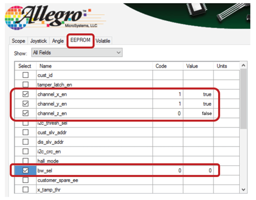
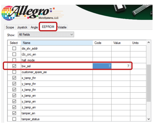
First the X and Y magnetic channels are enabled and the Z channel is disabled under the EEPROM tab. The Bandwidth Select value is set to code ‘0’ for full measurement resolution. Refer to the screenshot in Figure 2. Note: All channels come enabled from the Allegro factory.
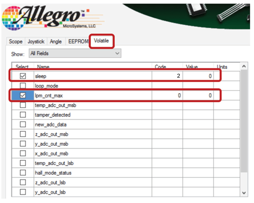
Next, set the value for LPM Count Max, which controls the duration of tINACTIVE. Referring back to Table 3, the appropriate code for tINACTIVE ≈ 500 μs is code ‘0’. With LPM Count Max set, the device may then be put into LPDCM by setting the Sleep field to a value of ‘2’. These volatile settings are shown in the screenshot in Figure 3.
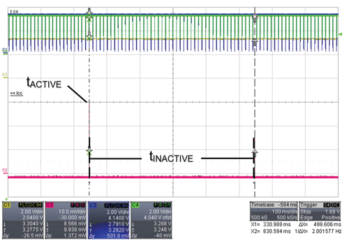
The resulting ICC profile is shown in the scope plot in Figure 4. Key parameters including inactive time (tINACTIVE), active time (tACTIVE), ICC(ACTIVE), and ICC(INACTIVE) are highlighted.
Note that the I2C commands are still processed even while the ALS31300 returns to the inactive state. This is possible because the I2C clock (SCLK) is processed in a separate domain from the
main system clock.
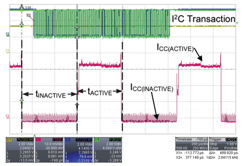
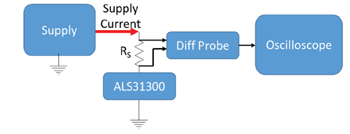
In Figure 4, ICC was observed by measuring a voltage across a series resistor on VCC using an oscilloscope with a differential probe (Figure 5).
Estimating ICC Consumption
The average current consumption can be estimated based on the scope plot in Figure 4 and the typical values for tACTIVE, tINACTIVE, ICC(ACTIVE), and ICC(INACTIVE). Recall that the duration tACTIVE
is the combination of settings for BW Select and the number of active channels.
The typical values for each of the parameters used in this example are summarized in Table 7.
Table 7: Typical Values for Key LPDCM Parameters
| Parameter Name | Typical Value | Units |
| tINACTIVE | 500 | μs |
| tACTIVE | 390 | μs |
| ICC(ACTIVE) | 3.4 | mA |
| ICC(INACTIVE) | 12 | μA |
For a complete table on timing versus BW Select and number of active channels, refer to Table 8 in Appendix A.
Current consumption may be estimated by the following equation, Average ICC in LPDCM:

Advanced Low Power Management Using the Interrupt Feature on ALS31300
The interrupt feature on the ALS31300 enables further system level power savings for applications requiring long battery life. This technique allows a system’s microcontroller to enter a low power state and wait for an interrupt from the ALS31300.
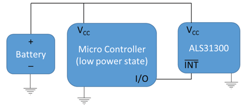
Assume that a system is monitoring for the presence of an applied magnetic field. For example, an electricity power meter may become inaccurate in the presence of large external magnetic fields. Assume this meter is sensitive to magnetic fields greater than 300 gauss (30 mT). Finally, assume there is a need for maximum current reduction in the system while on battery power due to a power blackout. A simplified block diagram is outlined in Figure 6.
Initialize Interrupt Conditions and ConfigureDevice for LPDCM
The ALS31300 interrupt thresholds may be configured independently for all three axes (X, Y, and Z). For this example, each axes threshold will be set to a value equivalent to 300 gauss.
During normal operation of the meter, the ALS31300 will be used in its full active mode, Sleep = 0, since power consumption is not as much of a concern. In this mode, the device is consuming its typical ICC(ACTIVE) at all times and continuously updating magnetic and temperature data.
Assume that the electricity meter detects a loss of power from the grid and reverts to battery backup, but it is still necessary to monitor for tampering events or large external fields. Since these events are interesting but not dangerous, we may choose to put the ALS31300 in its most efficient LPDCM.
First, set BW Select to the fastest state, code 7.
Next, configure the ALS31300 for one of its longest tINACTIVE times by setting LPM Count Max to code 6. Referring back to Table 3, we can see code 6 corresponds to a tINACTIVE time of 500 ms.
Average ICC consumption is again estimated in this mode using Equation 1 and substituting the symbols with typical values. Typical value for tINACTIVE with 3 channels enabled and BW Select = 7 can be found in Table 8 in Appendix A.
![]()
.
The system’s microcontroller may now be put into a deeper sleep state where it will be woken up by an active low by an active low Interrupt signal from the ALS31300 in the presence of field > 300 gauss.
The resulting ICC profile is shown in the scope plot in Figure 8. The duration of tACTIVE is so small in comparison to tINACTIVE that it appears as two small slits on the oscilloscope. I2C transactions
still occur during LPDCM.
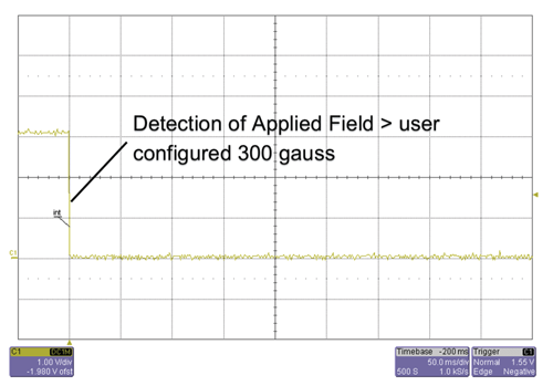
The scope plot in Figure 9 shows the Interrupt pin of the ALS3100 responding to an applied magnetic field > 300 gauss. The INT signal may be used as a wake up event for the meter’s micro, alerting the system to handle the tampering event.
APPENDIX A
The full table of typical values for active time (tACTIVE) based on BW SELECT settings and the number of active channels are shown in Table 8.
Table 8: Typical Active Times (tACTIVE) vs. Number of Active Channels and BW Select Values
| BW SELECT | Active Channels | Active Time (tACTIVE) (μs) |
| 0 | 3 | 592 |
| 2 | 390 | |
| 1 | 218 | |
| 1 | 3 | 313 |
| 2 | 224 | |
| 1 | 135 | |
| 2 | 3 | 188 |
| 2 | 141 | |
| 1 | 114 | |
| 3 | – | – |
| – | – | |
| – | – | |
| 4 | 3 | 263 |
| 2 | 191 | |
| 1 | 119 | |
| 5 | 3 | 164 |
| 2 | 125 | |
| 1 | 84 | |
| 6 | 3 | 114 |
| 2 | 91 | |
| 1 | 69 | |
| 7 | – | – |
| – | – | |
| – | – |
The information contained in this document does not constitute any representation, warranty, assurance, guaranty, or inducement by Allegro to the customer with respect to the subject matter of this document. The information being provided does not guarantee that a process based on this information will be reliable, or that Allegro has explored all of the possible failure modes. It is the customer’s responsibility to do sufficient qualification testing of the final product to insure that it is reliable and meets all design requirements.