Current Sensing for Power Delivery
Applications
• Telecom
Introduction
When it comes to electronics, power comes in many different forms and factors. Power rails can be AC or DC, as well as different voltage levels, current levels, and power limits. This results in a need for the conversion of power from one form or level to another. Recent technological developments such as fast DC charging for electric vehicles or high-power processors in data centers drive the need for higher power in smaller spaces. Whenever power is converted from one form to another, there is some form of power loss associated with the conversion that is dissipated as heat. Consumers, as well as certification bodies such as Energy Star™, demand a certain level of efficiency in their products or appliances to minimize wasted power. This leads power supply designers to wonder how to maximize power density as well as adhere to performance and efficiency requirements.
Active power factor correction AC/DC converters, switching DC/DC converters, and DC/AC inverters are all power conversion systems that face the above challenges and require current feedback to regulate properly and efficiently. This makes understanding current sensing and how it plays into overall system design and performance essential for power designers. This article will discuss the advantages of various current sensing methods in power delivery.
Current Sensing Methods in Power Conversion
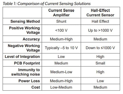
Some power conversion controllers have integrated current sensing, usually using an on-board amplifier connected to an external shunt. While this reduces design complexity, many integrated solutions are specialized for a specific application and do not allow for adaptation. Therefore, many topologies use a more generic microcontroller and external current sensing solution to send information back to the controller. Current sensing solutions typically seen in power conversion systems include:
• Traditional current sense amplifier and shunt
• Isolated amplifier and shunt
Shunt Solutions
Traditional shunt solutions can be cost-effective, but as accuracy requirements increase, so does the cost of the shunt which drives up total solution costs. Shunt solutions also offer superior accuracy at very low currents (<2 A) compared to magnetic sensing approaches. Current sense amplifiers are often limited by their common-mode voltage range. Common-mode voltage is the average voltage between the inputs of the current sense amplifier and usually ranges from negative several volts up to 100 V. Because the negative range is typical 2 to 10 V, traditional amplifiers cannot handle the negative voltage of an AC source. The 100 V positive maximum also limits traditional amplifiers in high-voltage DC applications unless the sensor is placed close to ground, which eliminates the ability to detect a short and creates a voltage drop from system ground and actual ground. Isolated amplifiers remove the limitation of sensing negative and high positive voltages but have reduced bandwidth and require an isolated supply that consumes layout space and budget. One drawback to any shunt solution is the dependence on shunt parameters such as tolerance, temperature drift, and parasitic inductance that affect overall system accuracy and performance. At high switching speeds common in power conversion, shunt inductance increases the overall shunt impedance. As frequency increases, so does the shunt impedance which will reduce the overall system accuracy and speed as well as cause output spikes.
Hall Solutions
Hall-effect current sensing is done by measuring the voltage (VHALL) across a biased Hall plate created by the magnetic field (B) of a current-carrying (I) wire (see Figure 1).
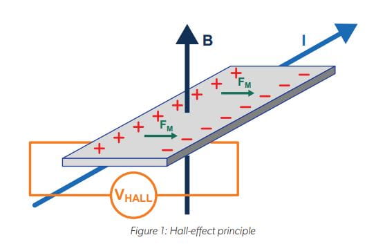
Hall-based solutions have the benefit of inherent galvanic isolation and working voltages up to >1000 V, so they can be used in AC and DC high-voltage applications without the need for a secondary isolated supply. Internal conductor Hall sensors are highly integrated and require no external shunt, which allows them to fit in tight layout designs. Additionally, because the sensing is done magnetically, the conductor inductance has no effect on the sensor output, which is especially helpful to mitigate output spikes when the current switches on and off. Another benefit is the low resistance of the internal conductor. This gives the Hall-based solutions lower power losses than the shunt-based ones and give the solution the advantage at higher current levels.
Power Factor Correction
Power factor correction (PFC) is a form of AC to DC conversion that aims to reduce reactive power and improve overall efficiency. In AC loads, power is equal to the instantaneous voltage times the instantaneous current. Inductive loads such as motors, coils, or transformers can cause the current to become out of phase with the voltage. This creates reactive power that is generated but does no actual work. Reducing reactive power increases overall system efficiency.
There are many PFC topologies including:
• Passive filtering techniques
• Boost PFC
• Dual boost bridgeless PFC
•Totem-pole bridgeless PFC
As efficiency requirements increase, so too does complexity and cost. Totem-pole topologies (see Figure 2) are becoming very popular due to their high efficiency, in some cases reaching above 99%.
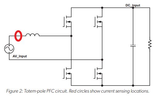
All active PFC topologies require input current and voltage sensing to regulate output and reduce phase separation. The high voltage requires an isolated solution such as the Hallbased or isolated amplifier. Switching speeds of PFC circuits are very high to reduce power loss. Speeds can range from 50 to 100 kHz and current sensor bandwidth is typically desired to be two to ten times faster than the switching speed to allow for adequate feedback. This corresponds to 100 kHz to 1 MHz current sensor bandwidth requirements. Isolated current sense amplifier solutions are typically limited to 300 kHz while Hall solutions can reach up to 1 Mhz.
Switching DC/DC Converters
Electronic circuits run on a wide range of DC voltages, hence the need for DC-to-DC conversion either on the AC/DC output or for systems with multiple DC rails. DC/DC topologies include but are not limited to:
• Buck
• Boost
• Buck-boost
• Flyback
• Resonant
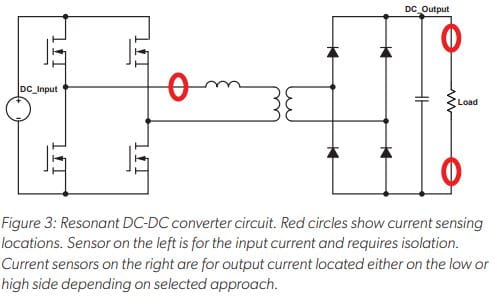
A resonant topology (see Figure 3) has the advantage of compact size, power density, and galvanic isolation, making it popular in EV charging and energy storage. Hall-based current sensing is particularly advantageous in high-voltage DC topologies with high-isolation requirements (>100 V). Switching frequencies and bandwidth requirements are similar for DC/DC when compared to PFC topologies, 100 kHz to 1 Mhz.
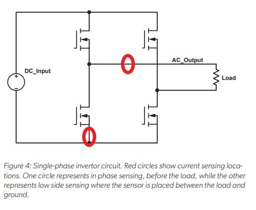
Inverters
Inverters (see Figure 4) take a DC voltage and transform it to an AC voltage. This is used when DC sources such as solar or batteries are being used to feed into the grid or for powerful AC motors. Inverters typically have lower switching speeds and require less bandwidth. Non-isolated current sensing solutions, such as traditional current sense amplifiers with shunts, can also be used in inverters, but the sensor must be place next to ground instead of in-phase with the AC output. This limits the ability to detect output shorts and creates a voltage drop from system ground and actual ground. This low-side sensor placement can only sense current when the low-side switch is on. In-phase isolated amplifiers or Hall-based solutions eliminate the ground difference, enable short detection, and can sense current regardless of switching state. This same concept can be applied to current sensor placement in motor control.
Copyright 2022, Allegro MicroSystems.
The information contained in this document does not constitute any representation, warranty, assurance, guaranty, or inducement by Allegro to the customer with respect to the subject matter of this document. The information being provided does not guarantee that a process based on this information will be reliable, or that Allegro has explored all of the possible failure modes. It is the customer’s responsibility to do sufficient qualification testing of the final product to ensure that it is reliable and meets all design requirements.
Copies of this document are considered uncontrolled documents.