Impact of Magnetic Relative Permeability of Ferromagnetic Target on Back-Biased Sensor Output
By Yannick Vuillermet,
Allegro MicroSystems Europe Ltd
Introduction
This application note aims to describe the target relative magnetic permeability impact on Allegro back-biased magnetic sensor output.
Sensor performance depends highly on the target mechanical geometry. In the case of speed applications, tooth and valley geometries are critical—but these mechanical properties are not the topic of this application note. Here, it is assumed that the target is well-designed for the customer application. Instead, this application note focuses on the target ferromagnetic material properties and especially the magnetic permeability.
The practical goal of this application note is to define the minimum target material relative permeability to guarantee optimum sensor performance in the application. This application note applies to any applications using a back-biased sensor associated with a ferromagnetic target: speed sensors (cam, crank, transmission, etc.), position sensors (linear, angle, etc.), etc.
Ferromagnetic Material Properties
A material is said to be ferromagnetic when it tends to acquire a magnetization when placed in an external field (from a permanent magnet, from a current in a coil, from earth field, etc.). In a ferromagnetic material, the material magnetization is aligned with the resulting internal field. On the contrary to permanent magnets, the remanent magnetization of a ferromagnetic material is very small when no
external field is applied.
Figure 1 is a simplified way of representing the above properties. In this figure, it is assumed that the material behavior is purely linear in low field and that there is no hysteresis (this is equivalent to no remanent magnetization here). H is the magnetic field, J is the magnetic polarization, Js is the polarization at saturation, and μ is the magnetic permeability. The magnetic polarization J is linked to the magnetization M with this relationship:
J = μ0 × M (1)
The relative permeability is defined as the permeability of the material versus the permeability of free space μ0:
 (2)
(2)
In the following, it is assumed that the material is only used in the linear range. This assumption is fully valid in most of the applications that Allegro sensors target. In this linear condition, μ – μ0 is the slope of the J(H) curve, and:
B = μ0 × μr × H (3)
Consequently, the only magnetic parameter that matters for the target material is the relative permeability, μr. Basically, the permeability represents the material capability to be magnetized by an external field.
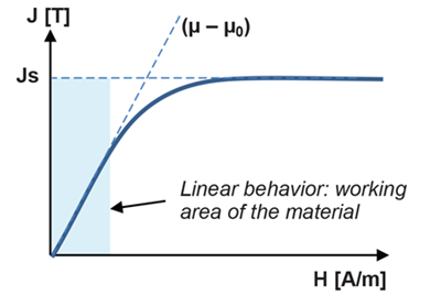
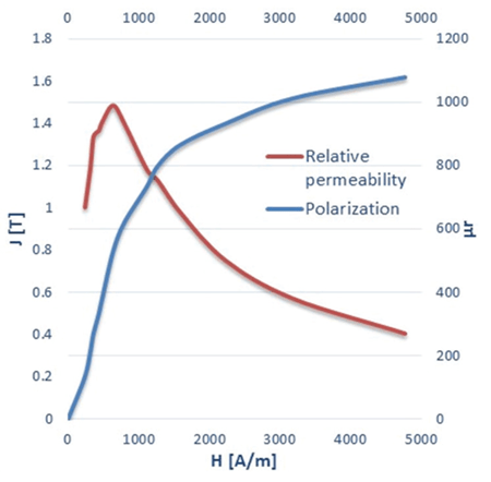
Figure 2 shows the measured data of steel1010, which is a classical material used in combination with Allegro sensors. It appears that the relative permeability of this material is always larger than 600 in the linear range of the material, that is to say, for H < 1000 A/m.
This 1000 A/m field value in the material, equivalent to ~12.5 Oe (oersted)—and which looks very small—must not be compared to the magnetic field in air, for example, produced by the back-biased magnet. A magnet can easily produce B-field of a few hundred gauss in air. However, a ferromagnetic material placed in this large B-field will have a much smaller internal H-field. As an example, for a magnet producing a 600 G field in air, a ferromagnetic material which has a relative permeability of 300 will typically only see a 5 Oe (or ~400A/m) H-field, according to equations 3 and 4, and to a typical form factor of 0.4 (see next section). This behavior is due to the demagnetizing field or, otherwise said, from the field that the material generates on itself. In summary, it is important to keep in mind that a large field in air from the back-biased magnet (few hundred gauss) does not necessarily imply that the ferromagnetic material works in its nonlinear mode.
This table gives the magnetic relative permeability of some common materials.
| Material | Magnetic Relative Permeability |
| Air | 1 |
| Copper | 1 |
| Neodymium magnet | 1.05 |
| Steel* | 1 to 4,000 |
| Permalloy | 8,000 |
| μ-metal | >20,000 |
Source: https://en.wikipedia.org/wiki/Permeability_(electromagnetism)
* Note that some steel variants are not magnetic, some stainless steel, for example.
Permeability versus Form Factor
The magnetization of a ferromagnetic material is driven by two main parameters: the magnetic permeability and the shape (form factor) of the object.
The following shows how these two parameters impact the magnetization on a very simple example.
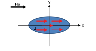
In the case of an ellipsoid object, the magnetization is uniform inside the material, whatever the uniform external field applied to the object. Note that this ellipsoid could be seen as a very rough approximation of a speed target tooth.
Figure 3 shows an ellipsoid placed in a uniform field Ho along x and the uniform magnetization J.
In this case, assuming there is no material magnetic saturation, the magnetization is given by:
 (4)
(4)
In this equation, Nx is the form factor of the ellipsoid along x. This parameter depends on the ellipsoid shape and is always below 1. An object elongated in the x direction will have a small Nx (for example Nx = 0.1). A specific case is the sphere which has Nx = 1/3.
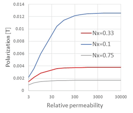
Figure 4 displays the object polarization versus the relative permeability for a few form factors. It clearly appears that objects elongated in the external field direction are easier to magnetize. More interestingly, one can notice that, above a given level of permeability, the object polarization only depends on the object shape. This clearly happens when 1 / (μr – 1) becomes negligible versus the form factor Nx.
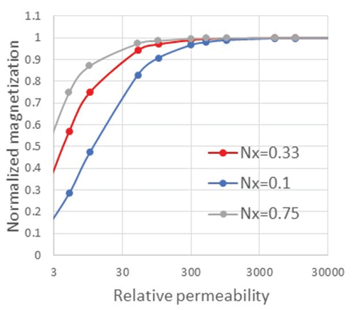
Figure 5 shows the same plot but with normalized polarization to better see the permeability level. It appears that, whatever the object shape, at least 95% of the maximum magnetization is reached as soon as the relative permeability is larger than 300.
This number will be confirmed in next paragraph in a realistic application.
Example of a Typical Application: Allegro 60X Reference Target with ATS699LSN Speed Sensor
Now, consider a typical speed application, using an ATS699LSN transmission part placed in front of the Allegro 60X reference target (Figure 6). ATS699LSN is a differential part which has three Hall plates (Left, Center, and Right) and two differential channels (Left-Center and Center-Right). The output of only one channel is considered in the following.
Typical working air gaps for this part are 1 mm and 2 mm, air gap being defined by the distance between the branded face of the sensor and the top of the target teeth.
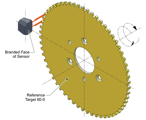
Figure 7 gives the normalized output of one channel when the target is passing in front of the sensor over one and half period. This graph shows that the differential field waveform is almost not dependent on the relative magnetic permeability. It can be observed that there is only a (small) difference between the waveforms when μr = 10 for positions around 3°. Positions around 0° have similar behavior whatever the relative permeability because these positions correspond to a valley of the target.
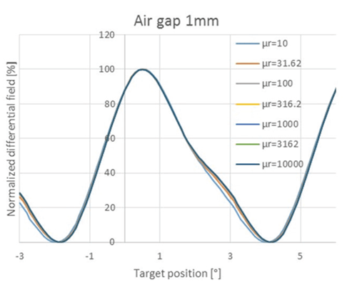
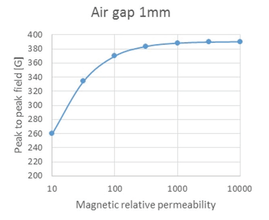
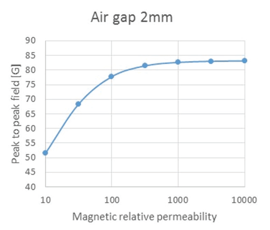
Figure 8 and Figure 9 give the peak-to-peak differential field of the channel versus relative permeability at 1 mm and 2 mm air gap respectively. These figures confirm what was seen earlier: to guarantee optimum performances, the target material relative permeability should be at least 300. Any further increase of relative permeability has a marginal impact on the magnetic signal measured by the sensor.
If the ferromagnetic target material has a relative permeability smaller than 300, it does not mean that the back-bias arrangement will not work. It will only work with degraded performance
compared to a target with large permeability. For example, the maximum working air gap of the application could be reduced.
Conclusions
Finally, this application note gives a simple answer to the question, “Is my target material suitable for a back-biased application?”: in order to have optimum performances, the magnetic relative permeability of the target material must be at least 300 for H-field < 2000 A/m.
However, this is a necessary but not a sufficient condition; having a proper target mechanical design is also mandatory to achieve application desired performances.
Allegro engineers can help evaluate whether the target’s material is adapted to a back-biased arrangement or not. If the material has a low relative permeability, Allegro can also provide support to estimate the impact on the application’s performance.