Overcoming Long-Term Reliability Challenges in Two-Wheeler Rear Combination Lamps
Introduction
In two-wheeler rear combination lamp (RCL) applications, LEDs are operated with varying brightness. Full brightness is used for braking, and low brightness is used for running the taillights. Mechanical switches at the handle brake and at the foot brake are subject to wear and tear, which is known to cause malfunctions in LEDs—from erroneous LED illumination to total failure. A noncontact switch solution can improve reliability compared to mechanical switches.
The typical two-wheeler RCL uses an LED array, a handle brake position sensor, a tail switch, and an LED driver. Automotive RCL applications are required to have two braking systems, so these systems must also support brake pedals. Tail switch and handle brake inputs—as well as brake pedal inputs, if included in the design—are connected as external input signals to the LED driver. When the handle brake or brake pedal is applied, the LED must respond instantly by switching two or three red LEDs in series—for larger arrays, multiple strings connected in parallel—from low current to high current. These systems typically require an operating supply voltage of 8 to 18 V, with transient specification per ISO 7637, and with reverse battery protection. Operation typically requires 150 to 300 mA in brake mode and 25 – 50% of that in taillight mode. Maintaining long LED life requires accuracy in these current transitions. In addition to meeting these requirements, for a design to build consumer confidence, it must be resistant to application challenges, including the introduction of water and debris. With all these concerns, finding a simple solution typically becomes another design challenge.
RCL Application Challenges
Water, Debris, and Corrosion
While LEDs are very reliable, failure of LED taillights due to damage from water and debris is relatively common. Seals that hold housings to protect internal systems wear out over time. When a seal begins to fail, corrosive elements like water and debris may enter and corrode system components, causing failures that may cause the LED to dim or burn out, or to remain on even when the vehicle is off. A broken brake light switch can also cause the taillights to remain powered on when the vehicle is off. The cause of rear brake lights that remain illuminated when they should turn off is usually a corroded component or debris in the brake pedal assembly. Solutions that can withstand debris and moisture that may become introduced into the system provide greater reliability.
Electrical Transitions and Design Complications
In mechanical switches, rainwater leakage can cause a small leakage current in LEDs. This can cause visible illumination that could be a safety risk. However, noncontact switch solutions completely eliminate this issue.
Maximizing operational lifetime requires excellent current management. LEDs should not be driven more than the specified current. Exceeding the specified current of an LED can produce brighter light, but it comes with the cost of reduced product lifetime. A dedicated LED driver can tightly regulate the current, simplify the design, reduce development time and risk of failure during testing or operation, and reduce cost, size, and weight.
The Noncontact Solution
To safeguard against failures from corrosion and debris, Hall-effect switches offer high-power and low-power RCL applications a silent, noncontact upgrade from failure-prone mechanically switched LEDs. A Hall-effect switch includes a Hall element that detects the presence or absence of a magnetic field. With a magnet (low-cost ferrite, for most RCL applications) placed parallel to the IC to create a magnetic field perpendicular to the IC, the position of the moving axis can be determined.
Low-Power RCL Applications
A unique solution from Allegro MicroSystems combines an LED driver and a Hall-effect switch in a single chip. The Allegro APS13568, designed for low-power RCL applications, provides minimum external components to deliver reliability and ease of design in RCL applications. A typical RCL application using the APS13568 LED driver and Hall switch assembly with the brake pedal (and incorporating the Allegro A1126 or APS11700 Hall-effect switch for the handle brake assembly) is shown and described in Figure 1. The PCB layout for RCL applications using the APS13568 and the surface temperature of the APS13568 operating three red LEDs at 140 mA at room temperature are also shown in Figure 1.
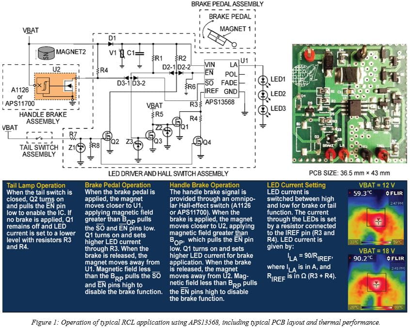
In the application shown, the APS13568 is placed below a magnet attached to the brake pedal. The magnet position is sensed by an internal omnipolar Hall switch. The omnipolar operation can detect magnetic field in either direction—north or south pole. This simplifies the placement of the magnet during production. Handle brake and tail switch inputs are connected as external input signals. The battery input is connected to VBAT, the handle brake signal is connected to BRAKE, the tail input is connected to TAIL, and LEDs are connected across LA and Ground.
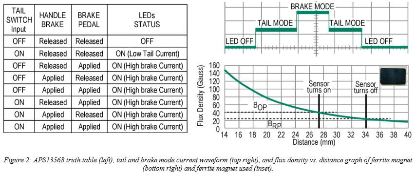
LED current is switched between low current and high current as the tail or brake inputs are applied. Switching occurs according to the operation logic shown in Figure 2, left. The output switches low when a magnetic field perpendicular to the Hall sensor exceeds the operate point threshold, BOP. When the magnetic field is reduced below the release point, BRP, the device output switches to high, as shown in Figure 2, right.
Magnet selection for the brake pedal depends on the BOP levels of the APS13568 and the air-gap requirement. A ferrite magnet of 27.5 mm × 18 mm × 6 mm27.5 mm × 18 mm × 6 mm size is recommended for this application. The magnet used in this example is shown in Figure 2, bottom right inset. The APS13568 sensor turns on at 27.3 mm (BOP = 40 G) and turns off at 34 mm (BRP = 25 G) as shown in the flux density graph in Figure 2, bottom right.
By using a Hall-effect switch that is integrated within the IC package, the chance that moisture or debris will be introduced when seals begin to show wear can be greatly reduced, thereby improving reliability.
High-Power RCL Applications
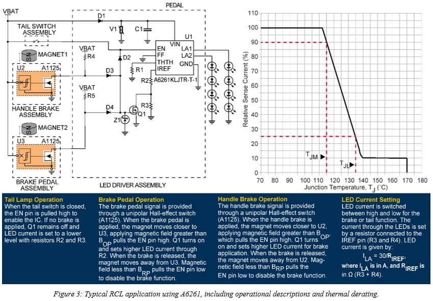
For higher-power RCL applications, the Allegro A6261 and A6263 LED drivers are used with Hall-effect switches to offer high-performance noncontact solutions. A typical two-wheeler high-power RCL using the A6261 LED array driver is shown in Figure 3. The LED current is set using the IREF pin through the R2 and R3 resistors. Allegro A1125 noncontact Hall-effect switches are used in the brake signals.
During operation, LED current drops with junction temperature. In the A6261 and A6263 devices, current levels and proper timing of electrical transitions are ensured by a programmable temperature monitor. The THTH pin sets the thermal derating threshold, TJM. This included temperature monitor function reduces the LED current with the silicon junction temperature, as shown for the A6261 device in Figure 3, which ensures optimized delivery of current for the application.
Conclusion
A range of LED drivers is available to meet the need for low- or high-power automotive RCL applications. The Allegro APS13568 offers a uniquely designed solution capable of both detecting pedal travel and driving illumination in a single package. For low-power RCL applications, this self-contained solution minimizes opportunity for corrosion from water and debris. The single IC design also makes the APS13568 an ideal choice for designers looking to save design time, board space, and cost. For high-power RCL applications or for larger LED arrays, the Allegro A6261 and A6263 LED drivers with a separate Hall-switch assembly offer a noncontact solution.
Using these LED drivers with integrated noncontact Hall-effect switches instead of mechanical switches can prevent corrosion and improve the reliability of LED systems in RCL applications.
Based on the article, "Improving Long-Term Reliability of Electric Bike Rear and Tail Light Combinations" by Ranjit Farakate, and Shashank Wekhande, originally published in EE Times China, May 9th, 2023. Republished with permission. For portions not copyrighted by original publisher, Copyright ©2023, Allegro MicroSystems, Inc.
Copyright 2023, Allegro MicroSystems
The information contained in this document does not constitute any representation, warranty, assurance, guaranty, or inducement by Allegro to the customer with respect to the subject matter of this document. The information being provided does not guarantee that a process based on this information will be reliable, or that Allegro has explored all of the possible failure modes. It is the customer's responsibility to do sufficient qualification testing of the final product to ensure that it is reliable and meets all design requirements.
Copies of this document are considered uncontrolled documents.