Advanced Hall-Effect Linear Current Sensor IC Enables High BW Sensing in Hybrid Electric Vehicles and other High Current Sensing Applications
Abstract
A new linear current Hall-effect sensor IC has been developed to accommodate the accuracy and bandwidth requirements of hybrid electric vehicle (HEV) inverter current sensing applications. The device uses a proprietary SIP package, and it employs next-generation chopper stabilization signal conditioning and filtering circuitry that combine to provide a low-noise, analog output signal at up to 120 kHz bandwidth. Industry leading accuracy levels are made possible by the introduction of proprietary, piecewise, linear temperature compensation that stabilizes the zero field offset and output sensitivity over the full operating temperature range without impacting the high bandwidth signal path. The device is ideal for all current sensing applications using a core configuration that require high frequency operation. The HEV inverter application is used as an example in this paper.
Introduction
A full bridge driver in a typical HEV inverter converts DC battery voltage to 3-phase AC voltage to drive an AC motor connected to the drive train (see Figure 1).
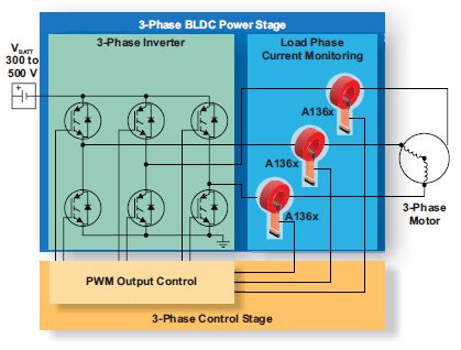
Figure 1: Typical Inverter Circuit Application
The inverter phase currents are measured, and the resulting information is used to control the pulse-width modulated (PWM) inverter switches (typically IGBTs). The inverter control loop requires high bandwidth current sensor ICs with high accuracy in order to maximize motor torque and overall motor efficiency. High side current sensor ICs with fast response times also enable over-current protection. The Allegro™ A1366 linear Hall-effect sensor IC has been designed to meet the high bandwidth, high accuracy requirements of HEV inverter applications. In these applications, the linear Hall-effect sensor IC is typically placed in the gap of a ferromagnetic “C” core, which surrounds each inverter phase conductor in the motor (see Figure 2). As current flows in the conductor, the core concentrates the resulting magnetic field through the single inline package (SIP).
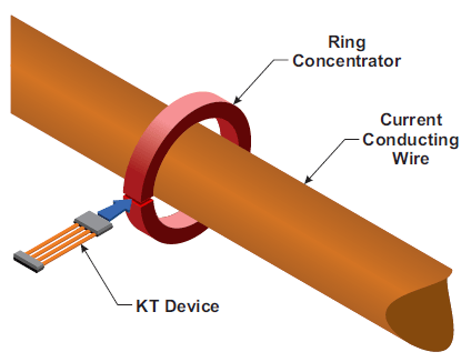
Figure 2: A1366 Current Sensing Configuration
Allegro’s proprietary design features make the A1366 an ideal sensor IC for use in HEV inverters, high current motor control, or any other high frequency, high current applications. These features include special packaging, advanced chopper and filtering techniques, and a digital temperature compensation algorithm. These innovations make possible an industry leading, high accuracy, 120 kHz bandwidth linear Hall-effect sensor IC that performs well in HEV current sensor applications.
This paper will focus on the next-generation package, as well as on the IC design innovations and their influences on sensor IC performance. It will also include a brief application discussion on core design.
Functional Description
Analog Signal Path and Bandwidth
Figure 3 shows a simplified block diagram of the A1366 linear Hall-effect sensor IC. The analog signal path of the sensor can be clearly seen. The analog output signal is ratiometric to the supply voltage, and it is nominally VCC/2 when the applied magnetic field is zero. The output will deviate from VCC/2 either in a positive or negative direction, depending on the polarity of the applied magnetic field or direction of current in the core configuration of Figure 2.
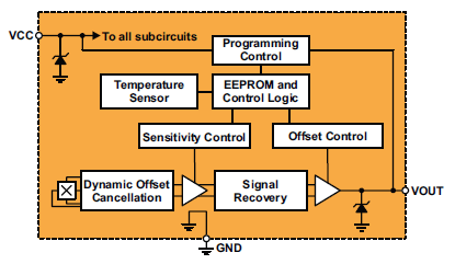
Figure 3: A1366 Block Diagram
The Hall element transducer generates a small signal that must be amplified with high gain. High amplification makes it difficult to create a stable output signal as the ambient temperature changes. The amplifier designs of the A1366 are made possible with a BiCMOS process that allows accurate amplifier design in conjunction with digital circuitry. The increased digital circuitry is used for factory programming at Allegro. Both the gain and offset can be adjusted over the operating temperature range. Furthermore, both the Hall element and the amplifier stages are chopper-stabilized to minimize the offset drift over temperature. Allegro has also developed proprietary chopper stabilization and notch filtering techniques that result in a low noise output, despite the large signal gain required in a linear Hall-effect sensor IC. In fact, the generational improvements in noise reduction are greater than an order of magnitude. The A1366 represents the highest bandwidth and highest resolution analog output sensors ever produced at Allegro. The six sigma peak-to-peak noise is approximately 6 mV at the full 120 kHz bandwidth.
The analog output response time of the A1366 is less than 4 μs, which is fast enough to protect IGBT devices from over-current or short circuit events. In lower frequency applications, the output can be filtered to lower the noise on the output and improve the resolution. The high bandwidth is made possible not only through the analog signal path design, but also the Single In-line Package (SIP), called the KT package.
Packaging
Normal SIP packages limit bandwidth due to the large amount of copper leadframe behind the Hall transducer. This metal pad allows eddy currents to form during faster dɸ/dt events. Eddy currents produce opposing magnetic fields on the leadframe. These fields slow down the response of the system and are reflected on the output of the linear Hall-effect sensor IC. The Allegro KT package removes the leadframe material directly behind the Hall element to eliminate eddy currents from the area of the Hall element. Without the modifications of the KT package, the higher bandwidth operation would not be possible. The Allegro proprietary package is highly effective and results in a 3 to 4X increase in the operational bandwidth of the A1366 in the KT package over the same IC used in a standard package.
The same packaging improvements are also available in an 8-pin TSSOP package for use in applications where customers have mechanical designs that require surface mount soldering.
Digital Temperature Compensation
In order to increase the overall accuracy of linear Hall-effect sensor ICs employed in current sensor applications, many suppliers have employed full digital signal paths. The disadvantage of digital filtering and signal conditioning is the loss of signal bandwidth, as the digital signal processing and signal conditioning lower the sensor bandwidth to the 1 to 3 kHz range, rendering them too slow for HEV inverter applications. Allegro has solved this issue with a new digital compensation scheme.
The A1366 accuracy is greatly enhanced with the addition of a proprietary digital temperature compensation algorithm that includes EEPROM technology. Piecewise linear temperature compensation between five boundaries is employed to drastically reduce the native drift of the analog signal path without sacrificing the signal bandwidth. Figure 4 illustrates the technique. Both quiescent field voltage output (QVO) and Sensitivity can be adjusted with the algorithm. The native drift of either QVO or Sensitivity is illustrated by the dotted line. The dashed line shows the linear compensation that is added between the boundaries, and the solid line shows the resulting behavior of the sensor output.
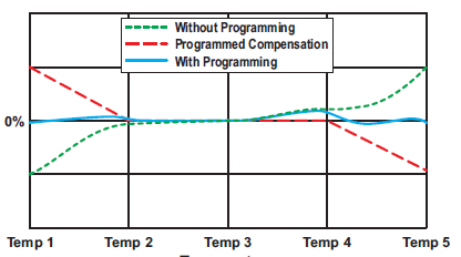
Figure 4: Temperature Compensation Algorithm Results
The A1366 has an onboard temperature sensor that determines the neighboring boundaries. A digital control engine applies the proper compensation.
Because the temperature change is very slow compared to the current being measured, the compensation scheme works in the background and constantly adjusts QVO and Sensitivity when necessary. In this way, the sensor analog signal path of 120 kHz is maintained, and the device accuracy is optimized.
The Allegro manufacturing group tests the device through the temperature range and programs the QVO and Sensitivity temperature compensation coefficients into the EEPROM, eliminating the requirement for customers to temperature test the final sensor assembly.
The A1366 QVO and Sensitivity absolute values are also programmed at the Allegro factory. Standard offerings for sensitivity include 1, 2.5, 5, and 10 mV/G. The device zero field output voltage QVO is programmed to 2.500 V. Allegro also has a customer programmable device – the A1363 – which is available for customers who need to program the device in their end application. The A1363 gives programming control over the absolute value of Sensitivity and QVO, which customers can program into the EEPROM at 25ºC at their end of line testing.
Core Design
As mentioned earlier, the A1366 linear Hall-effect sensor IC is designed to be used with a ferromagnetic core in a through-hole configuration (as shown in Figure 2) in HEV applications. Core material choice depends on the tradeoffs between:
- residual magnetism after signal excursion;
- the frequency response;
- the linearity of applied magnetic field versus applied current.
The most common choice is a laminated steel core. This is very cost effective and minimizes eddy currents, thus allowing excellent frequency response. The magnetic hysteresis of a laminated core is usually acceptable in most applications.
The cross-sectional area of the ferromagnetic core depends on the maximum amount of current to be sensed in the primary conductor. It also depends strongly on the choice of material. Care must be taken to ensure the material does not saturate at high temperature and produce non-linear response. Allegro applications support is available for customers that need help with core design and material selection.
A1366 Accuracy
The A1366 high programmability of QVO and Sensitivity, as well as the piecewise linear temperature compensation improvements, result in a 3X to 4X improvement over existing linear Hall-effect sensor ICs.
Sensitivity and QVO
The result of the techniques described throughout this paper combine in the A1366 to produce a high bandwidth, linear Halleffect sensor IC with nearly closed-loop accuracy performance in an open-loop sensor. Please see Figures 5 and 6 for graphs showing the performance of QVO and Sensitivity versus temperature. The graphs show a typical ±3 sigma sensitivity drift over temperature of less than ±1%, and a ±3 sigma QVO distribution of ±6 mV through the operating temperature range of –40ºC to 150ºC.
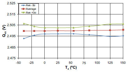
Figure 5: QVO versus Temperature
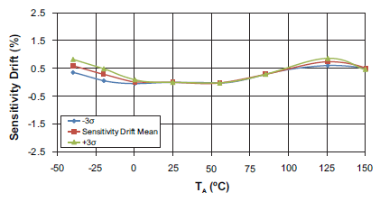
Figure 6: Sensitivity versus Temperature
Conclusion
The Allegro A1366 linear Hall-effect sensor IC has been designed for use in high accuracy and high bandwidth applications, such as those found in HEV inverters. The improvements in packaging, chopper stabilized amplifiers, advanced filtering, and innovative digital temperature compensation circuitry combine to provide a sensor IC with nearly closed-loop performance in an open-loop current sensor system. Low error levels that were once unachievable in even low bandwidth linear Hall sensor ICs are now achievable over a wide operating automotive temperature range and at bandwidths up to 120 kHz.
Article published in Hanser Automotive, February 2015. Reprinted with permission.
H2 { MARGIN-BOTTOM: 10px } H3 { MARGIN-BOTTOM: 10px } HR { MARGIN-BOTTOM: 10px } TABLE { MARGIN-BOTTOM: 10px } TABLE { BORDER-COLLAPSE: collapse } TH { PADDING-BOTTOM: 5px; PADDING-TOP: 5px; PADDING-LEFT: 5px; PADDING-RIGHT: 5px } TD { PADDING-BOTTOM: 5px; PADDING-TOP: 5px; PADDING-LEFT: 5px; PADDING-RIGHT: 5px }